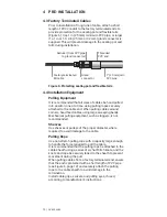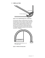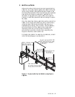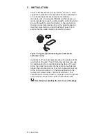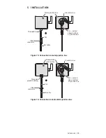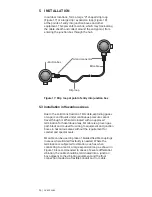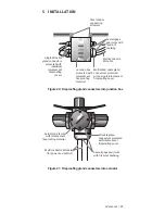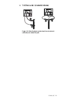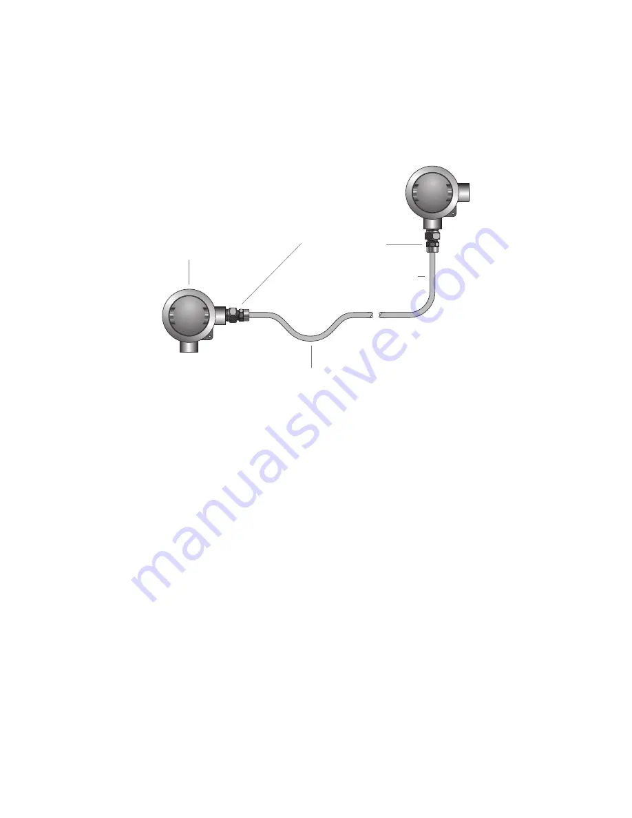
In outdoor locations, form a large “U” shaped drip loop
(Figure 17) or a large drip / expansion loop (Figure 18)
at the points of entry into junction boxes and other
equipment. This prevents moisture, which may track along
the cable sheath and collect around the entry point, from
entering the junction box through the hub.
Junction box
Gland connector
MI cable
Drip loop
Figure 17: Drip loop at point of entry into junction box
5.3 Installation in Hazardous Areas
Due to the solid construction of MI cable, exploding gases
or vapors and liquids under continuous pressure cannot
travel through it. When terminated with an approved
termination for hazardous areas, MI cable is a proven gas
path block and is used for wiring to equipment and junction
boxes in hazardous areas without the requirement for
conduit and special seals.
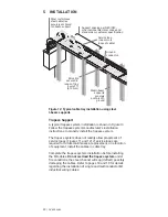
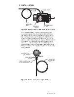
MI cable can be used in place of braided flexible couplings
in areas where limited flexibility is needed. Where the
termination is subjected to vibration, such as when
connecting to a motor, a large expansion loop as shown in
Figure 18 is recommended. In cases of severe differential
vibration, the cable should be terminated into a junction
box adjacent to the vibrating equipment and the final
connection made via a flexible conduit and / or cable.
5 INSTALLATION
26 | nVent.com
Summary of Contents for pyrotenax Alloy 825
Page 1: ...MI Cable Industrial Wiring Installation Manual For Alloy 825 Sheath Cables ...
Page 4: ...iv nVent com ...
Page 46: ...42 nVent com ...
Page 47: ...nVent com 43 ...

