background image

nVent.com  |  3

2 INTRODUCTION 

2.1 General

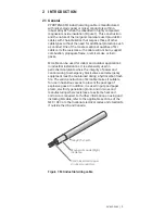
PYROTENAX MI industrial wiring cable is manufactured 

with nickel-clad copper or nickel conductors within a 

robust Alloy 825 sheath, embedded in highly compacted 

magnesium oxide insulation (Figure 1). This construction 

and the nature of the inorganic materials used provide MI 

cables with characteristics that surpass those of other 

cable types without the need for additional protection such 

as conduit. One of the most exceptional qualities of MI 

cable is its fire resistance—the cable will not burn, support 

combustion, propagate flame, or emit smoke or toxic 

gases.

MI cable can be used for indoor and outdoor applications 

in industrial installations. It is extensively used in 

petrochemical plants where the integrity of power and 

control wiring to emergency block valves and emergency 

equipment must be maintained during a hydrocarbon flash 

fire. The solid construction of MI cable makes it suitable 

for use in hazardous areas to prevent the passage of 

explosive gases. In addition, it is used in pulp and paper 

plants, electricity generation plants, and in mines and 

manufacturing where resistance to extreme heat and 

corrosion is required. For further information on using and 

installing MI cable, refer to the applicable sections of the 

NEC / CEC or other national electrical codes and standards 

if outside the US and Canada.

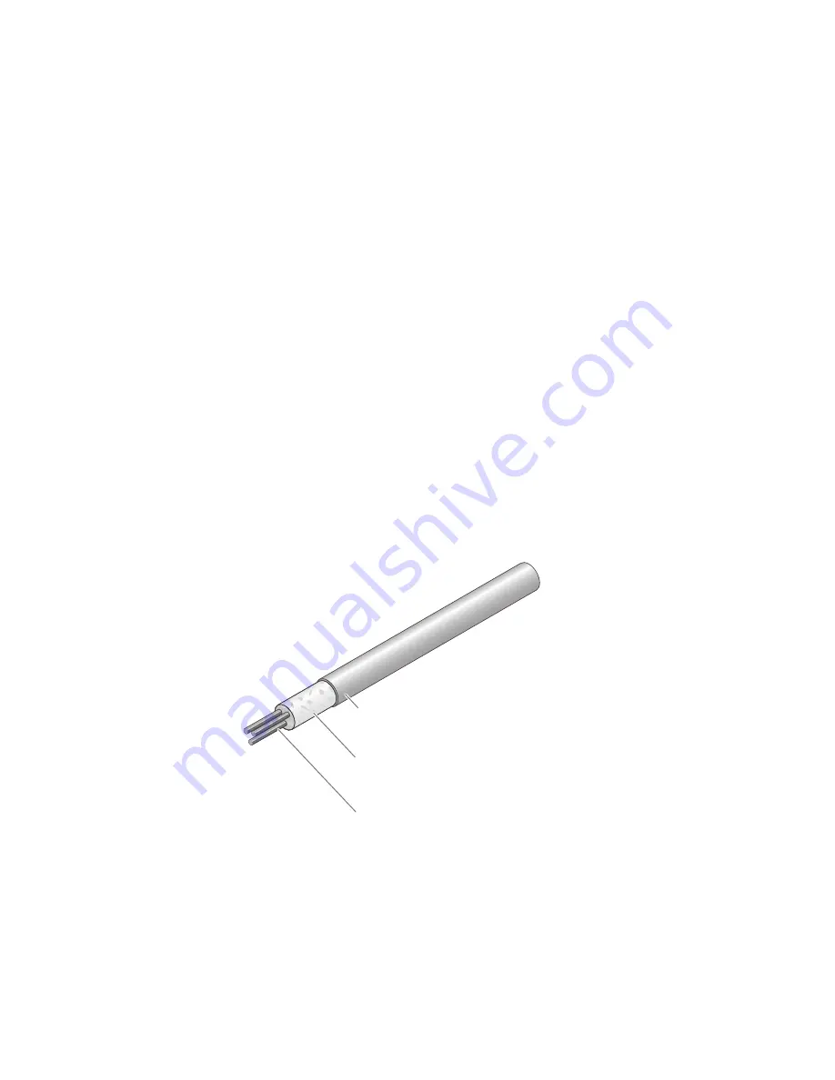
Solid nickel-clad copper 

or nickel conductors

Magnesium oxide (MgO)

insulation 

Alloy 825 sheath

Figure 1: MI industrial wiring cable

Summary of Contents for pyrotenax Alloy 825

Page 1: ...MI Cable Industrial Wiring Installation Manual For Alloy 825 Sheath Cables ...

Page 2: ...n dry covered area if possible During the time that the cables are exposed and during cable pulling activities protect cables from nearby or overhead work to prevent damage to the cable sheath Do not pull cables around corners that have sharp edges such as corners in cable trays or other obstructions Prevent damage to cables by removing any abrasions or sharp edges from surface of support system D...

Page 3: ... 2 Precautions 11 4 3 Factory Terminated Cables 12 4 4 Installation Equipment 12 4 5 Set Up 13 5 Installation 15 31 5 1 General Installation Guidelines 15 5 2 Connection to Junction Boxes and Other Equipment 23 5 3 Installation in Hazardous Areas 26 5 4 Protecting the MI Cable Terminations from Hydrocarbon Flash Fires 28 5 5 Cable Terminations 30 6 Testing and Commissioning 32 35 6 1 Tests 32 7 Tr...

Page 4: ...iv nVent com ...

Page 5: ... 527 5703 thermal info nvent com nVent com 1 2 Safety Guidelines The safety and reliability of an MI cable system depend on the proper design and installation of the system and use of proper materials for support as well as the quality of the cable selected Incorrect design or installation or use of inappropriate support materials can result in a system that may not perform satisfactorily and in t...

Page 6: ...ed Field installed termination kits for bulk cable are cCSAus Certified Note ATEX certified terminations also available 1 4 Warranty nVent s PYROTENAX MI wiring products Limited Warranty applies to these products For details see the complete warranty on our web site at nVent com Important For the nVent warranty and agency approvals to apply the instructions that are included in this manual and pro...

Page 7: ...or applications in industrial installations It is extensively used in petrochemical plants where the integrity of power and control wiring to emergency block valves and emergency equipment must be maintained during a hydrocarbon flash fire The solid construction of MI cable makes it suitable for use in hazardous areas to prevent the passage of explosive gases In addition it is used in pulp and pap...

Page 8: ... identification tag showing the cable specifications and approvals 2 3 Field Terminated Cables Cables that are to be terminated in the field are supplied with temporary heat shrinkable end caps that seal the ends against moisture ingress Field installed termination kits are available with the epoxy sealing compound or gray sealing compound shown in Section 5 5 page 30 and 31 and should be selected...

Page 9: ...the protective cover in place until removal is absolutely necessary Where possible check the cable sheath for evidence of shipment damage Verify that terminations or heat shrinkable end caps are not damaged missing or removed Verify that factory terminated cables are correctly labeled and have the appropriate gland connector fittings for the intended use Check the insulation resistance IR for the ...

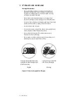
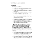
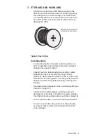
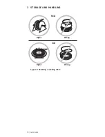
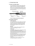
Page 10: ...rinkable end caps from bulk cable until the cable is ready to be terminated Do not stack coils or reels Do not store coils or reels flat Store coils upright and reels upright on their flanges Figure 2 Ensure that both ends of the cable are securely fastened to the reel flange Store reels on a firm surface paved if possible or on planking to prevent reels from rotting Always load and store reels up...

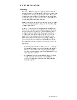
Page 11: ...reel and to the cable Take precautions to ensure that the flange of one reel does not impact the cable on another reel Note If a coil or reel is dropped or the protective covering is damaged examine the cable for damage Refer to Section 7 for the Troubleshooting Guide Damaged cables may need to be repaired or replaced Contact your local representative for more information The following lifting met...

Page 12: ...th a properly secured shaft extending through both flanges Cradle both reel flanges between fork tines Never drop reels Do not lift by a single reel flange Cable or reel may be damaged Never allow fork tines to touch the cable surface or reel wrap Figure 3 Reel handling DOs and DON Ts 3 STORAGE AND HANDLING 8 nVent com ...

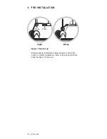
Page 13: ...t less easy to install Support reel on a jack stand when uncoiling cables supplied in coils may be fed from a pay off reel Figure 5 Have someone rotate the reel or coil to feed the cable as it is being pulled This will greatly ease the handling and prevent possible twisting bending and kinking Use appropriate precautions when uncoiling cable see Section 4 2 page 11 Handle cable carefully during un...

Page 14: ...Right Wrong Right Wrong Reel Coil Figure 5 Unreeling uncoiling cable 3 STORAGE AND HANDLING 10 nVent com ...

Page 15: ...fety regulations Therefore in addition to observing standard safety practices observe the following Take reasonable precautions to prevent damage to the cable from severe blows with sharp instruments and pulling over sharp objects Do not pull cables around corners that have sharp edges such as corners in cable trays or other obstructions Pull all cable diameters one at a time by hand Hand feed cab...

Page 16: ...pes securely attached to the cable end When pulling cables around corners hand feed cables using large sweeping bends Mechanical pulling equipment such as tuggers is not recommended Sheaves Use sheaves or pulleys of the proper diameter where required to avoid damage to the cable Pulling Rope Use non stretch pulling rope with a capacity large enough to handle the force required to pull the cable It...

Page 17: ...Figure 7 on page 14 The first sheave must be installed at a point higher than the support system Use a roller at the entry and exit points of the tray trapeze system The setup should ensure that the cable is not kinked or bent beyond the minimum pulling radius see Table 2 page 18 or subject to excessive twisting force Minimize the amount of tension necessary to pull a cable as follows Pull in the ...

Page 18: ... Roller Right Wrong Figure 7 Reel set up Station experienced cable pulling observers along the route in contact visually by radio or by phone with the other members of the crew 4 PRE INSTALLATION 14 nVent com ...

Page 19: ...g the IR to fall Low IR can be corrected as outlined in Appendix A Expansion and Vibration Where cables may expand or contract due to temperature changes or when connecting the cable to vibrating equipment it may be necessary to take precautions to prevent mechanical damage to MI cable Refer to Section 5 2 page 23 and Section 5 3 page 26 for further details Equipment Bonding The sheath of Alloy 82...

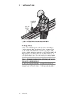
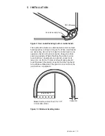
Page 20: ...t bends are kept as large as possible Where smaller bends are necessary a conduit bending tool Figure 9 may be utilized but care must be taken not to bend the cables to less than the minimum bending radius Table 1 Minimum Bending Radius for Permanent Training Cable O D outside diameter 0 75 in 19 mm and smaller 6 times cable diameter Larger than 0 75 in 19 mm 12 times cable diameter 5 INSTALLATION...

Page 21: ... small increments Shape into final position gradually When offsetting the cable to enter a junction box equipment via a gland connector at least 2 to 3 in 50 to 75 mm of straight cable should be left between the gland connector and the final bend to facilitate withdrawal of the gland connector from the junction box equipment see Table 1 Note Bending radius shown for 0 75 and smaller cables Cable O...

Page 22: ...nly and if space permits it is recommended that the cable pull begin at the equipment such as a valve actuator and that the cable be pulled from the unterminated end This will reduce the possibility of damage to the terminated end Table 2 Minimum Pulling Radius Cable O D outside diameter 0 75 in 19 mm and smaller 12 times cable diameter Larger than 0 75 in 19 mm 24 times cable diameter Multiconduc...

Page 23: ...ns of the NEC CEC or other national electrical codes and standards Multiple circuits should be appropriately spaced for ampacity considerations Where independent circuits are required or desired maintain proper separation and segregation from other electrical circuits Bundle single conductor MI cables tightly together every 2 ft 610 mm along the entire length of cable run in groups containing one ...

Page 24: ...d in the NEC CEC or other national electrical codes and standards Several support methods may be used however cable tray is recommended due to its wide availability and familiarity among installing contractors Cable Tray Figures 11 and 12 show two typical cable tray installation methods using open ladder trough type tray In Figure 11 the cable tray is supported using a rod and channel trapeze type...

Page 25: ...tie wire or adjustable gear clamps This ensures a neat installation prevents movement of the cables and is particularly important in the case of vertical runs of cable as it prevents the top section of cable from supporting the weight of the entire vertical cable run For further information on cable tray installations contact nVent Technical Support see Section 1 1 Steel channel MI cable secured t...

Page 26: ...igure 13 Follow the trapeze system manufacturer s installation instructions to properly install the trapeze system The trapeze system does not readily allow placement of service loops Figures 11 and 12 If service loops are required for future maintenance replacement or relocation of equipment install the cables in cable tray Complete the trapeze system installation before installing the MI cables ...

Page 27: ...amp with fasteners Steel or stainless steel washers and nuts Single conductor MI cable Steel rods securely anchored to fire rated structure Support spacing per NEC CEC other national electrical codes and standards or customer specification Multiconductor MI cable Figure 13 Typical installation using trapeze support 5 2 Connection to Junction Boxes and Other Equipment Locating junction boxes below ...

Page 28: ...nded to ground Figure 14 Typical ground bushing for nonmetallic enclosures only Install the pot so that it extends above the bottom of the junction box Figures 15 and 16 to prevent moisture due to condensation from contaminating the face of the pot Screw the gland connector into the junction box hub and tighten the compression nut rear nut on gland connector to the torque value shown on the tag su...

Page 29: ...on box Ground screw Threaded hub Figure 15 Connection to metal junction box Pot MI cable Gland connector Pot extend above bottom of junction box Nonmetallic junction box Ground screw Threaded ground bushing Figure 16 Connection to nonmetallic junction box 5 INSTALLATION nVent com 25 ...

Page 30: ...tinuous pressure cannot travel through it When terminated with an approved termination for hazardous areas MI cable is a proven gas path block and is used for wiring to equipment and junction boxes in hazardous areas without the requirement for conduit and special seals MI cable can be used in place of braided flexible couplings in areas where limited flexibility is needed Where the termination is...

Page 31: ...sure that the termination kit is the correct type for the area classification see Figure 22 on page 30 and Figure 23 on page 31 Use up excess cable by forming the cable into a loop as shown in Figure 19 All installations must be in compliance with the applicable requirements of the NEC CEC and any other applicable national or local codes and standards Five engaged threads Tighten gland connector t...

Page 32: ...nt Technical Support see Section 1 1 Note Junction boxes actuators valves etc must be protected as required by the customer specification In Figures 20 and 21 the junction box and valve actuator are in the fire zone and are protected with intumescent fireproofing material In both cases the MI cable gland connectors terminations must be protected with a similar fireproofing material at the points o...

Page 33: ...ing Multiple MI cable gland connectors protected with a single intumescent fireproofing cover Figure 20 Fireproofing gland connectors into junction box MI cable gland connectors protected with intumescent fireproofing cover Seal all gaps and joints with fireproof caulking Multiconductor MI cable for power and control Actuator protected with intumescent fireproofing material Figure 21 Fireproofing ...

Page 34: ...und Figure 22 is used to terminate cables located in nonhazardous Division 2 or Division 1 hazardous areas The Pyropak with gray sealing compound Figure 23 is used to terminate cables located in nonhazardous or Division 2 hazardous areas Prior to installing field terminations check the cable with a 500 V megohmmeter to ensure the IR is acceptable see Section 6 Follow the instructions supplied with...

Page 35: ...Cap and sleeve assemblies Gland connector Pots Gray sealing compound Figure 23 Termination kit with gray sealing compound 5 INSTALLATION nVent com 31 ...

Page 36: ...d correctly sealed and that the cable glands are tight and correctly fitted into junction boxes IR Test IR testing is conducted using a megohmmeter and tests the integrity of the cable between the conductors and the cable sheath and between conductor pairs in multiconductor cables If the terminations or heat shrinkable end caps are damaged missing or removed moisture will enter the mineral insulat...

Page 37: ...epair work minimum 25 MΩ Note If IR readings are low follow the instructions in Appendix A to dry out the cable Repairs Use only PYROTENAX MI cable and components when replacing any damaged cable Repairs should be performed only by qualified personnel and to nVent requirements Retest the system after repairs WARNING Damage to cables or components can cause sustained electrical arcing or fire Do no...

Page 38: ...to Step 7 If testing a multiconductor cable proceed to step 8 7 Testing is complete If the megohmmeter does not self discharge discharge phase connection to ground with a suitable grounding rod Disconnect the megohmmeter 8 If testing a multiconductor cable repeat steps 3 through 5 for remaining conductors 9 Next remove the positive earth lead from the cable sheath and connect it to one of the othe...

Page 39: ...500 1000 1500 2000 2500 500 1000 1500 2000 2500 Figure 24 IR test between cable sheath and conductor and between conductor pairs 6 TESTING AND COMMISSIONING nVent com 35 ...

Page 40: ... Arcing creat to the cable 5 Welding spla 6 Presence of termination seal 7 Damaged te temporary s Short circuits and direct earth faults 1 Physical dam is causing a from conduc 2 Misalignmen conductors w or incorrect completion stripping pro termination 3 Conductors sheath when only for unt cables 7 TROUBLESHOOTING GUIDE 36 nVent com ...

Page 41: ...ace cable or contact nVent technical support for assistance 6 Remove termination or temporary seal Dry out cable following the procedure in Appendix A Replace termination or seal 7 Replace termination or seal 1 Physical damage to cable is causing a direct short from conductor to sheath 2 Misalignment of the conductors within the seal or incorrect and untidy completion of the sheath stripping proce...

Page 42: ...f moisture is detected in the cable use an oxy acetylene or mapp gas torch with a large flame and heat out the cable beginning 12 in 300 mm back from the end Gradually stroke toward and past the cable end Alloy 825 sheath cables should be heated to a dull red color Take care not to overheat any one area of the cable sheath as this could damage the cable Use a short sweeping motion of the torch and...

Page 43: ...ame has been removed and the cable cools the IR will increase to an acceptable level if the moisture has been driven out On completion check IR with a 500 Vdc megohmmeter following the instructions in Section 6 If working with shielded twisted pair cable also test IR between the sheath and inner shield Reseal cable end with adhesive lined heat shrink tubing until ready to terminate cable nVent com...

Page 44: ...SULATION RESISTANCE TEST Receipt of Cables Note See Section 6 for minimum IR readings Cable Reference No Tag No IR Conductor to Sheath IR Co Performed by Company Witnessed by Company nVent 899 Broadway Redwood City CA 94063 USA Tel 1 650 474 7709 Fax 1 650 474 7711 info nvent com nVent com 8 APPENDIXES 40 nVent com ...

Page 45: ...c Accuracy full scale t of Cables dings IR Conductor to Sheath IR Conductor to Conductor Date Company Date Company Date Canada nVent 250 West St Trenton Ontario Canada K8V 5S2 Tel 1 800 545 6258 Fax 1 800 527 5703 nVent com 41 ...

Page 46: ...42 nVent com ...

Page 47: ...nVent com 43 ...

Page 48: ...demarks are the property of their respective owners nVent reserves the right to change specifications without notice RaychemPyrotenax IM INSTALL180 MI EN 1805 nVent com North America Tel 1 800 545 6258 Fax 1 800 527 5703 thermal info nvent com Europe Middle East Africa Tel 32 16 213 511 Fax 32 16 213 604 thermal info nvent com ...

Reviews: