background image

Moisture

seal

Moisture

seal

Moisture

seal

Moisture

seal

• Using glass cloth tape,  

attach heating cable to pipe.

• Apply insulation, cladding and warning labels.
• Terminate power wiring in user-supplied junction box.

• Using glass cloth tape,  

attach heating cable to pipe.

• Apply insulation, cladding and warning labels.
• Terminate power wiring in user-supplied junction box.

• Using glass cloth tape,  

attach heating cable to pipe.

• Apply insulation, cladding and warning labels.
• Terminate power wiring in user-supplied junction box.

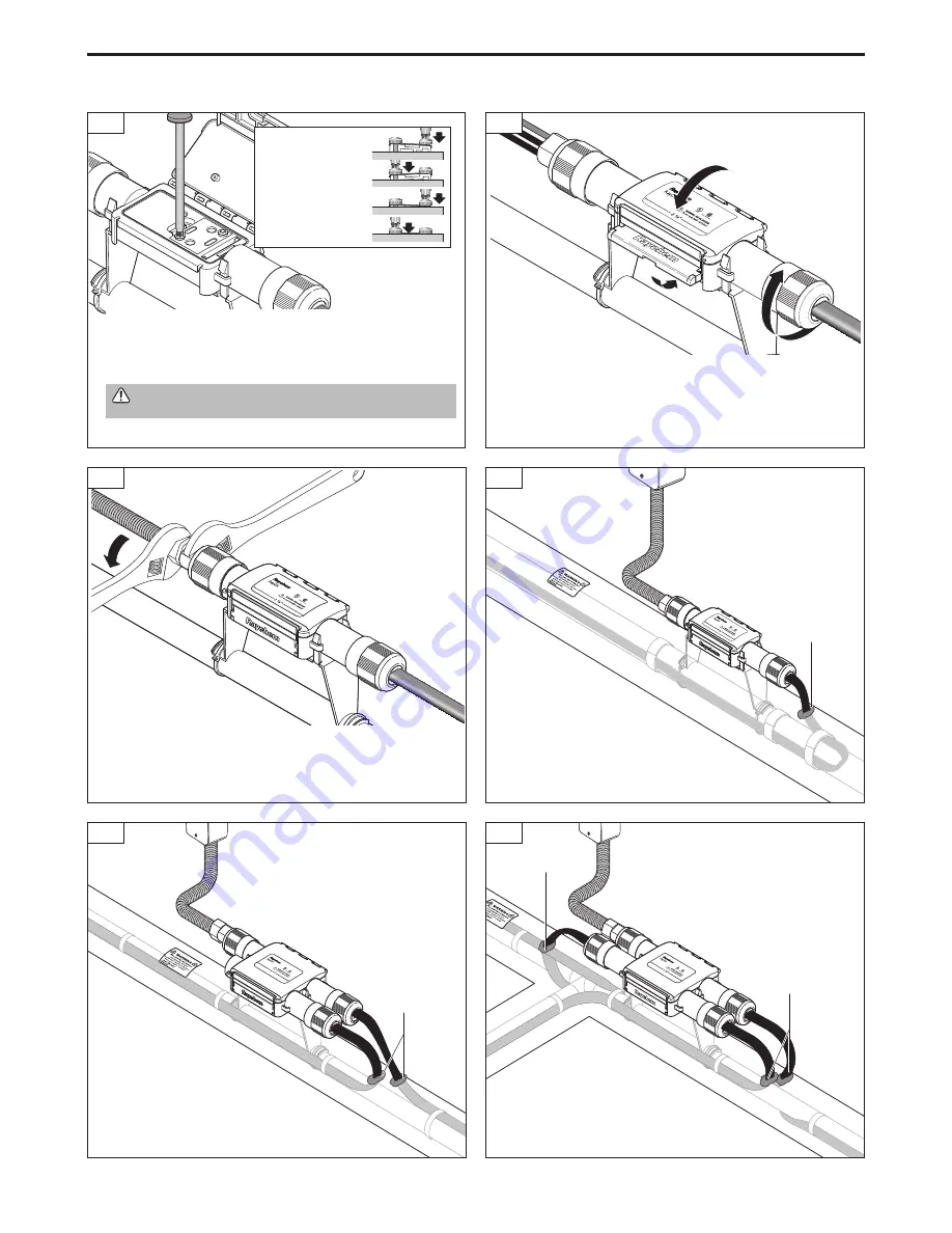
• Using two wrenches, attach user-supplied 1/2-inch conduit.  

To avoid breaking housing, do not exceed 15 ft-lbs of torque. 
Broken connectors must be replaced.

13B

13C

11

Power Connection 

• To prevent damage to heat-

ing cables, protect from 
sharp cladding edges.

• To prevent water ingress, seal 

the heating cable where it 
penetrates the insulation.

Powered Tee

• To prevent damage to heating cables, 

protect from sharp cladding edges.

• To prevent water ingress, seal the heating 

cable where it penetrates the insulation.

Powered Splice

• To prevent damage to heating cables, 

protect from sharp cladding edges.

• To prevent water ingress, seal the heating 

cable where it penetrates the insulation.

  WARNING: 

Fire hazard. Loose screws can cause excessive 

heating. Be sure screws are fully tightened.

• Securely tighten the two connection screws, alternating as they are 

being tightened.

• For Powered Splice and Tee kits, repeat steps 3 through 8 for all 

remaining heating cable entries.

Tighten the screws 

until the metal top 

surface is at the 

same height as the 

inner clear plastic 

module.

• Close the lid and snap the lever shut. Do not force lid closed; if lid does 

not close, check the connection to ensure all screws are fully tightened.

• Tighten the nuts on the heating cable entries until grommets are com-

pressed.

4

RayClic-PC, RayClic-PS, RayClic-PT Installation Instructions

10

13A

12

Summary of Contents for RayClic-PC

Page 1: ...Arcing may not be stopped by conven tional circuit breakers Bus wires will short if they contact each other Keep bus wires separated Keep components and heating cable ends dry before and during installation The black heating cable core is conductive and can short It must be properly insulated and kept dry Component approvals and performance are based on the use of Tyco Thermal Controls specified p...

Page 2: ...Clic PT powered tee fold up two center snaps then position the connector over the snaps and press down Allow enough extra heating cable to make service loops as required Make sure the end of the heating cable is cut clean For the RayClic PC power connection fold up the four outer snaps then position the connector over the snaps and press down Power Connection Splice and Tee Installation 3 1 8 For ...

Page 3: ... 3 1 8 1 9 For HWAT only Apply HWAT label on insulated hot water tank Using wire cutters cut away 1 inch of the braid Pull exposed braid back over metal clip IceStop and XL Trace HWAT 7 Using wire cutters cut away aluminum wrap Note RayClic connection kits are designed to be installed only once the heating cable cannot be removed once installed Apply a small amout of lubricant to the jacket surfac...

Page 4: ...es the insulation Powered Tee To prevent damage to heating cables protect from sharp cladding edges To prevent water ingress seal the heating cable where it penetrates the insulation Powered Splice To prevent damage to heating cables protect from sharp cladding edges To prevent water ingress seal the heating cable where it penetrates the insulation WARNING Fire hazard Loose screws can cause excess...

Page 5: ...Apply Electric De Icing and Snow Melting label on or near junction box RayClic PC RayClic PS and RayClic PT Mount flat wall mounting bracket under eaves by installing screws through the center holes Do not mount in gutter or where it may be immersed in water Position attachment clips on mounting bracket based on the type of the connector being installed Connect heating cable as detailed in steps 3...

Page 6: ...p and XL Trace Note The end seal is designed to be installed only once it cannot be removed from the heating cable once installed Do not use until ready for final installation HWAT H W A T IceStop and XL Trace 2A 3 Score around and down the outer jacket 1 inch from the end Remove the outer jacket Do not cut or damage the inner jacket Using wire cutters cut away aluminum wrap close to braid and out...

Page 7: ...s Braid clip does not fit Be sure the clip is installed on the metal braid not on the outer jacket Heating cable does not have Only HWAT heating cables have the aluminum wrap under the braid Skip the aluminum wrap aluminum wrap removal step for XL Trace and IceStop heating cables Heating cable cannot be Check for the following inserted into connector Apply cable lubricant to the heating cable prim...

Page 8: ...ntrols only obli gations are those in the Tyco Thermal Controls Standard Terms and Conditions of Sale for this product and in no case will Tyco Thermal Controls or its distributors be liable for any incidental indirect or consequential damages arising from the sale resale use or misuse of the product Specifications are subject to change without notice In addition Tyco Thermal Controls reserves the...

Reviews: