background image

2  |  nVent.com

1

2B

2A

Prepare the conduit and pull rope.

•  Verify that major construction is complete.
•  Verify conduit and pull rope has been installed 

properly. Reference TraceTek document 

H58175 for general information.

Note that conduit dimensions and related parts can vary 

between projects.

•  Verify that the pull rope is free of knots and splices 

and that there is 6 feet of extra rope at both ends of 

each section.

•  Two people are needed to manage the pull rope. One 

person is on each end of the end pull rope, and each 

person must be able to communicate with the other in 

case of problems during the pull.

•  The person feeding the pull rope into conduit needs to 

maintain slack at all times.

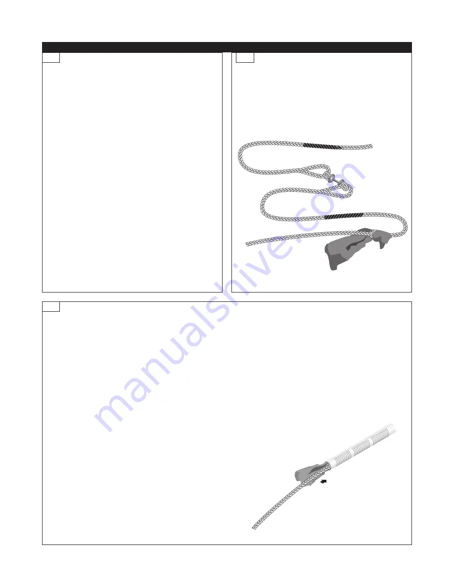
•  Pull the sizing tool from one end of the conduit  

section to the other. 

•  Verify that the sizing tool pulls freely through 

each section of conduit. Pull with a slow steady 

motion. Do not use excessive force on the pull 

rope, as this could damage the conduit.

•  As you pull, coil the pull rope by hand and keep the 

pull rope out of the dirt by placing it on cardboard or 

plastic sheeting.

•  If the pull rope becomes stuck, do not increase 

pull force-instead pull the rope in opposite 

direction for a short distance, then try repulling 

in original direction with normal force.

•  Shake the rag attached to the sizing tool free of excess 

debris. Remove the rope section containing the rag 

from the sizing tool. Replace the rag with a clean rag if 

necessary, and then attach the rope section with the rag to 

the eye splice in advance of the sizing tool.

•  Reverse the pulling direction to bring the sizing tool 

through the conduit in the opposite direction, and return the 

original pull rope back into the conduit. Remove the sizing 

tool and rope section with rag from the pull rope.

•  Verify conduit ends are marked for example, with different 

color conduit endcaps or tape to indicate direction 

(towards or away) relative to TraceTek alarm module.

•  Arrange excess pull rope by coiling around the riser pipe 

and taping in place.

•  Cover conduit ends to maintain cleanliness within conduit. 

Use a plastic bag taped in place, or stuff a clean rag into 

conduit end.

Conduit Cleaning:

•  Even if the conduit was proofed with a conduit cleaning 

tool during the conduit installation process, it is 

recommended to clean and check clearance of the 

conduit immediately before installing cable in order to 

avoid damaging the cable.

•  Attach a rope section with a rag tied to the eye splice in 

advance of the sizing tool. 

Installation

Summary of Contents for TRACETEK TT5000-HS

Page 1: ...mination Used during installation or trouble shooting to temporarily isolate a sub section of sensor cable for resistance measurements nVent RAYCHEM TraceTek TT Kellems Grip Large part P000001291 Large Kellems Grip used in cable pulling when rope overbraid loop not available nVent RAYCHEM TraceTek TT ULTRA TORCH part 390067 000 Flameless heating tool Ultratorch 200 or suitable heat gun with concen...

Page 2: ...ll the rope in opposite direction for a short distance then try repulling in original direction with normal force Shake the rag attached to the sizing tool free of excess debris Remove the rope section containing the rag from the sizing tool Replace the rag with a clean rag if necessary and then attach the rope section with the rag to the eye splice in advance of the sizing tool Reverse the pullin...

Page 3: ...f cable into the conduit Before pulling the cable into any conduit verify that correct conduit is being used Good conduit installations will use a strategy to mark conduits Check with project supervisors if any doubt exists as to how the conduit is labeled Errors in conduit identification and cable orientation can result in compromised cable quality Insert the end of the rope braid as far as possi...

Page 4: ...normal force Finish the cable pull by extending the TT500X HS MC with factory installed connectors or TT5000 HS HYB HSE with factory installed end termination cable at least 1 foot beyond top of the access point conduit riser For TT500X HS bulk sensing cable without connectors cable extend at least 2 feet beyond top of the access point conduit riser The extra length is necessary due to connectoriz...

Page 5: ...zed cable or as part of the TT5000 HUV CK MC M F connector kit Install the heat shrink tube as environmental seal over all mated male female pin socket connections Center the unlabeled shrink tube over the pin socket connection Heat shrink the tube over the connection beginning in the center and shrinking towards the ends until the tube fully conforms to the shape of the connection and adhesive fl...

Page 6: ...sensing cable following the Sensing Cable Test Procedure If practical connect the installed sensing cable to the TraceTek alarm module Test the system and put it in operation following the alarm module installation instructions At the beginning of the next work day Check that the installed sensing cable is clean and intact following the Sensing Cable Test Procedure Compare the results with those o...

Page 7: ...ries a cable string ensure they are all connected 2 Connect a Modular Leader Cable TT MLC MC to the sensing cable 3 Verify that the sensing cable is intact Loop 1 Measure the resistance between the yellow and black wires of the leader cable as illustrated Loop 2 Measure the resistance between the red and green wires of the leader cable The readings should roughly equal a multiple of the length of ...

Page 8: ...ngths and is also available in bulk form for long distance runs between the sensor cable and alarm module location F Install a leader cable TT MLC MC BLK between the sensor cable and the alarm module location The factory standard length of leader cable is 12 ft 4 m It has a female metal connector on one end and four tinned leads on the opposite end for connection at the alarm module terminal block...

Page 9: ...ons until the cable continuity is established and the Normal condition is achieved Leak testing can be done with a mapping cap TT MAPPING CAP MC or by bending the sensor cable tightly between fingers The MAPPING CAP simulates a leak at the location where it is installed in the system For TTSIM 1 a red LED will indicate that the simulated LEAK has been detected For TTDM 128 a leak location will be ...

Page 10: ...module instructions for more information For Cable break indication Check for loose connectors missing end terminations broken jumper wires or physical damage to the cable Repair or replace cable if necessary The TT MET MC end termination can be used to isolate a damaged section by working outward from the instrument using the end termination to establish a temporary end of the circuit then sequen...

Reviews: