background image

nVent.com  |  5

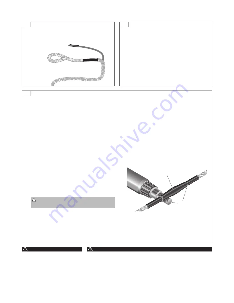
Tape

SCT

SCT

Unlabeled heat-shrinkable tube

Adhesive visible at

ends of tubing

6

5C

7

Prior to installing a new length of sensor cable, slide the 

unlabeled shrink tube (from connector kit) onto the cable. 

Connect the sensing cable to the cable circuit (lengths of 

sensing cable connected in series) previously installed.

•  Mark the connector position on the layout plan.
•  Install TraceTek mapping tag (TT-TAG).
• 

Note

: As an extra precaution on large installations, 

periodically test the entire cable circuit to confirm that all 

installed sensing cable is still clean and intact.

•  Unplug the end termination and connect it to the next 

length of sensing cable to be installed.

Repeat the installation sequence for each length of cable.

•  Grasp the sealed end and pull about 12 inches (30 cm) of 

sensor cable out while holding the rope braid in place.

•  Tape the rope braid to sensor cable to prevent the rope 

from springing back.

Complete the system

1.  Install other TraceTek components (such as Modular 

Branching Connectors, Weighted Lengths, and Modular 

Jumper Cables) as called for in the system layout. 

Complete the sensing circuit.


Note

: All components of the system have male or female 

metal connectors or both. The male connectors are oriented 

toward the instrument panel. As new sections of cable are 

added to the main leg or branch, each newly added section 

should end with an open female connector. The end of each 

branch or main leg is terminated with a male end termination.

2.  Test the sensing circuit (or portions of it) to confirm that 

the sensing cable is clean and intact. Follow the Sensing 

Cable Test Procedure.

3.  Locate the unlabeled heat shrink tubing segment (delivered 

along with the TT500X-HS connectorized cable, or as part 

of the TT5000–HUV–CK–MC–M/F connector kit.) Install 

the heat shrink tube as environmental seal over all mated 

male/female (pin/socket) connections.

•  Center the unlabeled shrink tube over the pin/socket 

connection. Heat shrink the tube over the connection, 

beginning in the center and shrinking towards the ends 

until the tube fully conforms to the shape of the connection 

and adhesive flows from each end of the tube.

  CAUTION: Burn Hazard. Do not get hot adhesive on 

your bare skin. The hot adhesive will burn your skin.

•  Avoid overheating the thin wall unlabeled shrink tubing. 

The thin wall tubing requires less heat than the SCT cable 

shrink tubing.

• 

Let the entire connector area cool before handling the cable.
Note: Do not leave connector open to environment. If 

the connector becomes wet or contaminated, it will need 

to be replaced.

Note

: When arranging any TT500X-HS cables do not use a 

bend radius less than 2 in. (51 mm).

Note

: If a heat-shrinkable tube must be removed (for 

example, for cable testing), refer to Oversleeve Removal 

Instructions (H54258).

4.  Connect the sensing circuit to the TraceTek alarm module 

and activate the system as soon as is practical. Use the 

alarm module to monitor for events during the final stages 

of construction.

FIRE HAZARD

. Heat guns and flameless heating 

tools can cause fire or explosion in hazardous 

areas. Be sure there are no flammable materials 

or vapors in the area before using these tools. 

Follow all site safety guidelines when working in 

hazardous areas.
Component approvals and performance are based 

on the use of specified parts only.

HEALTH HAZARD

. Overheating heat-shrinkable 

tubing will produce fumes that may cause 

irritation. Use adequate ventilation and avoid 

charring or burning. Consult MSDS RAY3122 for 

further information.

CHEMTREC 24-hour emergency telephone:  

(800) 424-9300
Non-emergency health and safety information:  

(800) 545-6258

.

WARNING:

CAUTION:

Summary of Contents for TRACETEK TT5000-HS

Page 1: ...mination Used during installation or trouble shooting to temporarily isolate a sub section of sensor cable for resistance measurements nVent RAYCHEM TraceTek TT Kellems Grip Large part P000001291 Large Kellems Grip used in cable pulling when rope overbraid loop not available nVent RAYCHEM TraceTek TT ULTRA TORCH part 390067 000 Flameless heating tool Ultratorch 200 or suitable heat gun with concen...

Page 2: ...ll the rope in opposite direction for a short distance then try repulling in original direction with normal force Shake the rag attached to the sizing tool free of excess debris Remove the rope section containing the rag from the sizing tool Replace the rag with a clean rag if necessary and then attach the rope section with the rag to the eye splice in advance of the sizing tool Reverse the pullin...

Page 3: ...f cable into the conduit Before pulling the cable into any conduit verify that correct conduit is being used Good conduit installations will use a strategy to mark conduits Check with project supervisors if any doubt exists as to how the conduit is labeled Errors in conduit identification and cable orientation can result in compromised cable quality Insert the end of the rope braid as far as possi...

Page 4: ...normal force Finish the cable pull by extending the TT500X HS MC with factory installed connectors or TT5000 HS HYB HSE with factory installed end termination cable at least 1 foot beyond top of the access point conduit riser For TT500X HS bulk sensing cable without connectors cable extend at least 2 feet beyond top of the access point conduit riser The extra length is necessary due to connectoriz...

Page 5: ...zed cable or as part of the TT5000 HUV CK MC M F connector kit Install the heat shrink tube as environmental seal over all mated male female pin socket connections Center the unlabeled shrink tube over the pin socket connection Heat shrink the tube over the connection beginning in the center and shrinking towards the ends until the tube fully conforms to the shape of the connection and adhesive fl...

Page 6: ...sensing cable following the Sensing Cable Test Procedure If practical connect the installed sensing cable to the TraceTek alarm module Test the system and put it in operation following the alarm module installation instructions At the beginning of the next work day Check that the installed sensing cable is clean and intact following the Sensing Cable Test Procedure Compare the results with those o...

Page 7: ...ries a cable string ensure they are all connected 2 Connect a Modular Leader Cable TT MLC MC to the sensing cable 3 Verify that the sensing cable is intact Loop 1 Measure the resistance between the yellow and black wires of the leader cable as illustrated Loop 2 Measure the resistance between the red and green wires of the leader cable The readings should roughly equal a multiple of the length of ...

Page 8: ...ngths and is also available in bulk form for long distance runs between the sensor cable and alarm module location F Install a leader cable TT MLC MC BLK between the sensor cable and the alarm module location The factory standard length of leader cable is 12 ft 4 m It has a female metal connector on one end and four tinned leads on the opposite end for connection at the alarm module terminal block...

Page 9: ...ons until the cable continuity is established and the Normal condition is achieved Leak testing can be done with a mapping cap TT MAPPING CAP MC or by bending the sensor cable tightly between fingers The MAPPING CAP simulates a leak at the location where it is installed in the system For TTSIM 1 a red LED will indicate that the simulated LEAK has been detected For TTDM 128 a leak location will be ...

Page 10: ...module instructions for more information For Cable break indication Check for loose connectors missing end terminations broken jumper wires or physical damage to the cable Repair or replace cable if necessary The TT MET MC end termination can be used to isolate a damaged section by working outward from the instrument using the end termination to establish a temporary end of the circuit then sequen...

Reviews: