nVent.com | 7
Sensing Cable Test Procedure
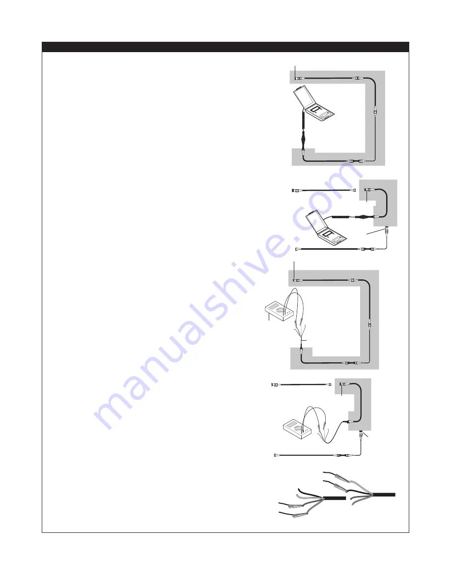
Method with nVent RAYCHEM TraceTek Portable Test Box
(TT-PTB-1000)
1. Ensure the end termination is connected to the sensing cable.
If checking several lengths of sensing cable in series (a cable
string), ensure they are all connected.
2. Connect the PTB to the sensing cable(s) using its
adapter, as illustrated.
3.
Verify that the sensing cable is intact;
follow the operating
instructions printed inside the lid of the PTB itself. If a cable
or connection is broken, the PTB illuminates its LED indicating
“cable break,” and displays a “1” in the leftmost position of its
LCD display. If the cable string is intact, the PTB measures the
system length.
• If the cable string is not intact, apply this test procedure to
segments of the system to identify the open connection or
damaged modular length.
•
Note
: If a heat-shrink tube must be removed to
access a connector, refer to Oversleeve Removal
Instructions (H54258).
4.
Check the condition of the sensing cable(s),
again following
the PTB operating instructions. If the sensing cables are clean
and free of contamination, the current measured should be
0 µA. If the reading exceeds 10 µA, use the PTB to locate the
liquid or contamination and take appropriate corrective action.
Method with Ohmmeter
1. Ensure the end termination is connected to the sensing cable.
If checking several lengths of sensing cable in series (a cable
string), ensure they are all connected.
2. Connect a Modular Leader Cable (TT-MLC-MC) to the
sensing cable.
3.
Verify that the sensing cable is intact:
• Loop 1: Measure the resistance between the yellow and black
wires of the leader cable as illustrated.
• Loop 2: Measure the resistance between the red and green
wires of the leader cable.
The readings should roughly equal a multiple of the length of
sensing cable:
4.0 times the length of sensing cable (in feet), or 13.1 times
the length of sensing cable (in meters).
Example:
4.0 x 50 ft of cable = 200 Ω
13.1 x 15 m of cable = 197 Ω
In addition, the resistance of the two loops should be within
5 percent of each other.
If the cable string is not intact, apply this test procedure
to individual segments of the system to identify the open
connection or damaged modular length.
Note
: If a heat-shrink tube must be removed to access a
connector, refer to Oversleeve Removal Instructions (H54258).
4.
Check the condition of the sensing cable
. Measure the
resistance between the black and green wires of the
leader cable.
If the reading is below 20 megohms, apply this test procedure
to individual segments of the system to identify the modular
sensing cable length(s) affected, locate the damage or
contamination, and take appropriate corrective action.
End termination
End termination
Testing an
individual
length of
cable
Testing a
cable string
End
termination
PTB
TRACE
TEK
TRACE
TEK
Testing an
individual
length of
cable
Testing a
cable string
End
termination
TT-MLC-MC
Ohm
meter
End termination
End termination
To yellow
To black
To red
To green


