background image

RCT150A Operator • Service • Maintenance Manual

84

Specifications

REV:

0.1

25 / 39

MAN_serie600_IS.doc

6.4  Riduttore fornito con olio 

Prima della 

messa in funzione, verificare il livello dell'olio 

lubrificante. Se necessario effettuare il 

riempimento o il rabbocco

.

Qualora il riduttore sia già fornito con olio lubrificante 

al giusto livello (come definito in fase d'ordine), 

attenersi alle istruzioni riportate in dettaglio ai 

paragrafi "

Riempimento olio

" e "

Scarico e 

sostituzione olio

" solo per i cambi olio successivi 

alla messa in esercizio. 
Il tipo di olio lubrificante è riportato nel disegno di 

installazione del prodotto. 

6.4  Gearbox factory filled with oil 

Before the 

starting up, check the level of lubricating oil. If 

necessary, refill with lubricant oil. 

In case the gearbox is factory filled with lubricant oil 

at level (as specified when ordering) ,follow the 

procedures given in detail at sections "

Oil filling

" and 

"

Oil draining and replacement

" only for the oil 

replacements following the start up and running in. 
The lubricant oil type is shown on the product 

installation drawing. 

6.5  Caratteristiche dell’impianto oleodinamico 

Il motore idraulico viene lubrificato con l’olio del 

circuito idraulico che deve rispondere alle 

caratteristiche

ISO VG 46

. Esso deve essere filtrato 

con grado massimo di 

10 µm

 e con livello di 

contaminazione uguale o inferiore alla 

classe 9 

secondo NAS 1638 

oppure

22/18/15 secondo 

ISO/DIS 4406

.

E’ opportuno non mescolare fra loro olii con proprietà 

differenti.
E’ consigliato usare un filtro con indicatore visivo 

d’intasamento visibile dall’esterno, con una valvola 

limitatrice che blocchi il flusso dell’olio quando il filtro 

sia intasato. 
Qualora si dovesse lavorare a basse temperature, 

(climi artici) sono necessarie norme specifiche 

(contattare il costruttore). 
Il controllo della temperatura dell’olio idraulico è una 

delle costanti più critiche nel sistema idraulico. 
Alte temperature di esercizio, causano un degrado 

della resistenza all’ ossidazione ed accelerano il 

deterioramento dell’olio idraulico. 
Osservare quindi le seguenti precauzioni : 

1.

La temperatura dell’olio idraulico in esercizio 

continuo di lavoro si mantenga in un campo fra i 

25°C÷90°C

.

2.

La temperatura di messa in funzione deve essere 

possibilmente al di sopra di 

-20°C

.

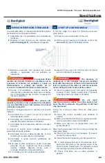
3.

Durante l’esercizio, e solo per brevi momenti, l’olio 

può raggiungere, ma non superare, la temperatura 

di

90°C

.

Questi valori di temperature sono stabiliti in base a 

considerazioni generali sul degrado della viscosità e 

sugli additivi antiusura dell’olio. 
La vita del motore subirà una notevole riduzione se la 

temperatura di esercizio in continuo sarà superiore 

agli

90°C.

6.5  Characteristics of the Hydraulic System

The hydraulic motor lubrication must reflect the ISO 

VG 46 characteristics. It must be filtered with a 

maximum grade of 

10 µm 

and with a contamination 

level equal to or inferior to 

class 9 according to 

NAS 1638 

or

22/18/15 according ISO/DIS 4406

.

Hydraulic fluids with different properties should not be 

mixed. 
Use filter with a visual indicator which can detect 

clogging from the outside, and with a reliefvalve 

which by-passes the oil when the filter element is 

clogged.
Should the machine operate at very low temperature 

(artic climates) it is essential to use specific 

guidelines (contact the manufacturer). 
As the temperature of the hydraulic oil may be a 

critical factor we recommend that it be checked. 
High operational temperatures will causea corruption 

of the oxidation resistance level and will accelerate 

the deterioration process of the hydraulic oil. 
The following precautions should be taken: 

1.

The temperature ranges of the hydraulic oil during 

operation have to be within 

25°C

÷

90°C.

2.

The temperature of oil should reach

 -20°C

 prior to 

start operation. 

3.

During operation the oil temperature can rise to 

90°C

 but this temperature is acceptable only for 

very short periods of time. 

These temperatues have been set to take into 

consideration general degrading in viscosity as well 

as the wear resisting additives used in the oil. 
The lifetime of motor will be reduced significantly if it 

should continuously above 

90°C

.

Summary of Contents for RCT150A 2019

Page 1: ...RCT150A OPERATOR SERVICE MAINTENANCE MANUAL RAYCO MANUFACTURING 2019 ALL RIGHTS RESERVED PRINTED IN USA INDEX OSMRCT150A 19 Serial Number RCT150A0010719 and Above ...

Page 2: ...machine Readandunderstandallinstructionsbefore attempting to operate this machine This manual should be readily available for reference at all times Additional copies of this manual may be purchased from Rayco This Rayco machine was designed and manufactured by RaycoManufacturing Inc Wooster Ohio Duetocontinuous improvements Rayco reserves the right to make changes in engineering design and specif...

Page 3: ...RCT150A Operator Service Maintenance Manual 800 392 2686 3 Content TABLE OF CONTENTS Forward 4 Safety 8 Operation 22 Maintenance 32 Troubleshoot 48 Warranty 87 ...

Page 4: ...a guide to equipment care The Maintenance Interval Schedule lists the items to be maintained at a specific service interval The Maintenance Interval Schedule lists the page number for the step by step instructions required to accomplish the scheduled maintenance procedure Maintenance Intervals Use the service hour meter to determine servicing intervals Calendar intervals shown daily weekly monthly...

Page 5: ...8 2018 EGR Rollers and Idlers Lifetime Lubrication Drive Sprocket 20 Tooth Track Rollers 8 each side Track Rubber 700mm 27 72 x 100 x 98 Ground Pressure Carrier only 2 28psi 15 7kPa Ground Pressure Max Carrying Capacity 4 psi 27 6kPa Travel Speed We High Range 6 8MPH Maximum Low Range 4 1MPH Maximum CAN Display Panel We Fuel Level Engine Coolant Temperature Tachometer Voltmeter Hour Meter Diesel E...

Page 6: ...mple RCT150A 001 07 19 RCT150A Type of Rayco equipment you have 001 Three digit for the number of produced 02 Two digit month 01 Jan 02 Feb etc 14 Two digit year 14 2014 15 2015 etc It is attached to the machine at the location shown For ready reference record it in the boxes provided on the inside front cover of this manual For reference on communication regarding the engine record its model and ...

Page 7: ...nance Manual 800 392 2686 7 Serial Number Location Information Identification Numbers Model Number Serial Number Machine Engine Implement Implement Dealer Information Name Address Dealer Contact Phone Number Hours Sales Parts Service ...

Page 8: ...allprotectiveguardsandallcoversaresecured in place on the equipment Keep the equipment free from foreign material Remove debris oil tools andotheritemsfromthedeck fromwalkways and from steps Secure all loose items such as lunch boxes tools and other items that are not a part of the equipment Knowtheappropriateworksitehandsignalsandthepersonnel that are authorized to give the hand signals Accept ha...

Page 9: ...echnique not specifically recommended by Rayco you must use it only if you have accurately evaluated it and found that it threatens no one s safety You should also ensure that the product will not be damaged or made unsafe by the operation lubrication maintenance or repair procedures that you choose The procedures described in this Safety section may not be fully explained here but a more complete...

Page 10: ...ectionmustconformtoANSIZ87 1andbethewrap aroundstyle Alwaysweartheeyeprotectionwhenoperating or working within the operational area of the machine Hearing Protection Plug type ear protection or full ear coverage devices muff type shall be worn at all times when operating or within the operational area of the machine Gloves When operating or handling brush within the operational area of the Horizon...

Page 11: ...ined during performance of inspection maintenance testing adjusting and repair of the equipment Prepare to collect the fluidwithsuitablecontainersbeforeopeninganycompartment or disassembling any component that contains fluids Tools that are suitable for collecting fluids and equipment that is suitable for collecting fluids Tools that are suitable for containing fluids and equipment that is suitabl...

Page 12: ...come to a complete stop before opening access covers and or guards Stay clear of all rotating and moving parts A moving belt pulley sprocket and chain can suddenly pull a limb into them causing loss or severe injury If it is necessary to remove guards in order to perform maintenance alwaysinstalltheguardsafterthemaintenance is performed Keep objects away from moving fan blades The fan blade will t...

Page 13: ...e a fire Fire may cause personal injury and property damage Remove all flammable materials such as fuel oil and debris from the machine Do not allow any flammable materials to accumulate on the machine Serious personal injury can occur when fuel or oil is spilled on yourself or your clothes which can ignite Storefuelsandlubricantsinproperlymarkedcontainersaway fromunauthorizedpersons Storeoilyrags...

Page 14: ...starting aid for cold weather starting Lines Tubes and Hoses Do not bend high pressure lines Do not strike high pressure lines Do not install any lines that are bent or damaged Repair any lines that are loose or damaged Leaks can cause fires Consult your Rayco dealer for repair or for replacement parts Check lines tubes and hoses carefully Do not use your bare hand to check for leaks Use a board o...

Page 15: ...ue to pressure buildup caused by an increase in temperature For your safety repair or replace all damaged or worn parts immediately Replacement parts which are authorized by Rayco are the only parts which should be used for repair or replacement on this machine Altering this equipment or using this equipment in such a way as to circumvent its design capabilities and capacities could result in seri...

Page 16: ...up alarm and all other warning devices are working properly Fastentheseatbeltsecurely ifequipped Lowerthearmrest Operation Onlyoperatethemachinecontrolswhentheengineisrunning Do not leave the operators station while machine is running Before you move the machine you must be certain that no one will be endangered While you operate the machine and the work tool slowly in an open area check for prope...

Page 17: ...traction and machine s stability Rocky surfaces may promote side slipping of the machine Slippage due to excessive loads This may cause downhill tracks or downhill tires to dig into the ground which will increase the angle of the machine Width of tracks or tires Narrower tracks or narrower tires further increase the digging into the ground which causes the machine to be less stable Implements atta...

Page 18: ...right type and size of machine equipment and attachments Maintain machines according to the manufacturer s recommendations a Tire pressures b Brake and steering systems c Controls hydraulic system and linkages Keep the terrain in good condition a Remove any large rocks or obstacles b Fill any ditches and holes c Provide machines and schedule time in order to maintain the conditions of the terrain ...

Page 19: ...ld also be closed Safety glasses are recommended when flying hazards exist for machines with cabs and machines with open canopies If the work material extends above the cab top guards and front guards should be used Additional guards may be required for specific applications or work tools The Operation and Maintenance Manual for your machine or your work tool will provide specific requirements for...

Page 20: ...n essential items 4 Inform all affected personnel 5 Check to see that all affected persons are located in a safe position 6 Inform the worker of the lockout tag out removal before the worker starts to work for his her next shift 7 When more than one person works on the same equipment multiple lock tag outs must be used Only when all locks are removed can the equipment be energized Pre Transportati...

Page 21: ...ffic Loading Your Combination NEVER load cargo inside the vehicle in tow or on the trailer Cargo inside the vehicle in tow can cause sway or WHIPPING NEVER overload your tow vehicle Do not exceed the Gross Vehicle Weight Rating GVWR and the Gross Axle Weight Ratings GAWR which are posted on a label inside the driver s door opening Make sure the trailer is securely attached to the tow vehicle hitch...

Page 22: ...Exterior 1 Engine Compartment 2 Fuel Fill Neck 3 Hydraulic Tank Location 4 Cab 5 Dumpbed 6 Rear Idler 7 Carrier Roller 8 Track Rollers 9 Travel Motor Sprocket 10 Rubber Track 11 Head Lights 12 Battery Location 13 Main Power Disconnect Battery Jumper Post 14 Radiator 1 2 5 3 4 6 7 8 10 11 12 13 14 9 ...

Page 23: ...olded up if required and the height individually adjusted 5 Backrest Adjustment The backrest is adjusted using the lever The locking lever must latch into the desired position It should not be possible to move the backrest into another position when it is locked 6 Seat Heater The seat heater switch can be found on the left side of the seat just behind the lumbar The heater switch can be turned on ...

Page 24: ...The track carrier s dump bed comes equipped with a tail gate spring that will automatically open and close the tail gate When the dump bed begins to elevate the tail gate will swing open When the dump bed begins to descend it will automaticallylatchshutonceitsflatontheframeofthecarrier To raise the dump bed press the top button on BOTH dump bed switches simultaneously To lower the dump bed back do...

Page 25: ...well as menu options for setup and configuration Soft Keys The soft keys correspond to the soft key commands and allow selections to be made accordingly The soft keys will time out To activate the soft key guide simply press one of the soft keys Menu Key The bottom right key is a soft key reserved in most cases for the Menu In rare cases it could be used for other options Pressing the MENU key at ...

Page 26: ...s go out you may start the engine START Turn the key to this position and hold to crank the engine Releasing the key will allow it to return to the ON position The engine will not start unless the safety interlocks are engaged The safety interlocks are as follows Operator must be in the seat Seat belt must be latched Parking Brake needs to be in the ON position Once the engine is running if any of...

Page 27: ...icator lamps frequently during warm up and operation Undercoldconditions thehydraulicfilterrestrictionindicator lamp may come on Under extremely cold conditions the hydraulic filter may shut down the track transmissions and all hydraulic functions As the hydraulic oil warms up the track functions should return and the hydraulic filter restriction indicator lamp should go out If after the oil has w...

Page 28: ...rting the engine Unexpectedmovementcancausedeath personal injury or property damage 10 Do not start the engine or move any of the controls if there is a DO NOT OPERATE or similar warning tag attached to the machine 11 Check with the local utilities for the locations of buried pipes and cables where applicable before operating the machine 12 Clear all personnel from the machine and from the area 13...

Page 29: ...re that no personnel are between the machine and the trailing equipment Blockupthehitchofthetrailingequipmentin order to align the hitch with the draw bar Maneuver the machine Connectthemachinetothetrailingequipment Know the maximum dimensions of your machine Always keep the Rollover Protective Structure ROPS installed during machine operation Never exceed the maximum ROPS rating Always keep body ...

Page 30: ...ess to a convenient location forrepair Theseinstructionsareonlyforemergencies Always haul the machine if long distance moving is required To disengage the track drives remove the bolts that secure the drive sprockets to the wheel drives This will allow the tracks to turn independently of the motors Block the tracks securely so that the machine cannot move The towing connection must be rigid or tow...

Page 31: ...s in poor condition maximum towing machine capacity is required Transportation Information Shipping the Machine Investigate the travel route for overpass clearances Make sure that there is adequate clearance for the ROPS FOPS structure Remove ice snow or other slippery material from the loading dock and from the truck bed before loading Removing ice snow or other slippery material will prevent the...

Page 32: ...g the amount of time for that next interval to the time when performing that maintenance as suits the occasion Then as you frequently compare the actual service hours to the record you will be properly informed to the maintenance requirements as time passes Themaintenanceintervalslistedinthis Maintenance Intervals section of this Operator Manual includes engine care topics For the complete informa...

Page 33: ...RCT150A Operator Service Maintenance Manual 800 392 2686 33 Maintenance Maintenance Log Date Machine Hrs Description of Service Maintenance Notes ...

Page 34: ...rack Tension check X Air Cleaner Ejector Valve Clean X Hydraulic Oil Filters Change X X X Engine Mounts Inspect X X Engine Oil Filter Change X X Fan Belt Tension check check Fuel Filter Change X X Fuel Water Separator Element Change X X X Pump Gearbox Bolt Tightness Inspect X X Track Bolts Re Torque check X Master Link Bolts if equipped Re torque X X Track Motor Sprocket Bolts check check Track Dr...

Page 35: ...of the machine and its hydraulic components Check the engine oil level the hydraulic oil level and the fuel level Air Cleaner Elements Clean Replace Cleanorreplacethefilterelementsevery100hrsorasneeded depending on conditions The air cleaner is located on the opposite side of the cab facing the bed in the engine compartment Toaccesstothefilterelement unfastenthethreeclamps 1 on the end cover as sh...

Page 36: ... OR HIGH PRESSURE WATER FOR CLEANING WITH A HOT WATER CLEANING DE VICE USE A SPRAY STEAM WITH A PRESSURE NOT EXCEEDING 426 PSI 2982 KPA TO PRE VENT DAMAGE TO PAINTED AR EAS OF THE COMPONENTS THE USE OF SOLVENTS OR STRONG CLEANERS SHOULD BE AVOIDED FOR THE FIRST 90 DAYS STRONG CLEANERS WILL DESTROY PAINT UNTIL THE PAINT IS FULLY CURED REFER TO PAGE 52 OF THIS MANUAL FOR INSTRUCTIONS ON CLEANING THE...

Page 37: ...37 Dump Bed Hinges The dump bed hinges 3 are below the bed Track Roller Pivot Shafts The track roller pivot shafts 4 or positioned on each track above the rollers There are 4 on each side with a total of 8 grease zerks that will need serviced Maintenance 3 4 ...

Page 38: ...elly or dielectric grease around base of terminal replace the cable Brake System Test The brakes on your RCT150A consist of hydrostatic braking and spring applied hydraulically released parking brakes If the machine has hydrostatic power to climb a slope it has sufficient hydrostatic power to brake the machine To test the parking brake Climb a slope with the machine Stop on the slope and observe t...

Page 39: ...lve 9 and turn the valve handle counter clockwise to drain The valve is located on the bottom of the machine located under the engine Drain all the oil out of the engine Remove the oil fill cap 8 to aid in draining 2 Using a filter wrench remove the oil filter 7 on the machine and replace with a new one Rayco part 801394 Apply a light coat of oil on the seal onto the threads of the filter 3 Replac...

Page 40: ...the element gradually plugs with contaminants resultinginnoticeablepowerlossand orhardstarting When any one occurs change the element as soon as possible Always carry an extra replacement element as one tankful of contaminated fuel can plug a fuel filter Element replacement procedure To change an element first loosen the large black retaining ring Pull the element straight down do not twist the el...

Page 41: ...rrect size open end wrench remove the suction strainers from the side of the hydraulic reservoir This must be done from the bottom by removing the center belly pan Clean and inspect the strainers Replace them if they are worn plugged or damaged Replacethestrainersandmakesuretheyareseatedsecurely Hydraulic Oil Change 1 Clean the pumps motors cylinders hydraulic lines fittings and tank 2 Place the m...

Page 42: ...stant lubricationatstart up Alsoremovetophoseconnection of the HC Hydraulic Cylinders pump fill with oil and reinstall top hose connection This will provide instant lubrication to HC pump at start up 6 PlacingthepumpControlinNeutralatstart upisessential to prevent any unexpected machine movement 7 Run the Prime Mover engine for a short period of time using the starter Crank the engine briefly repe...

Page 43: ...at normal operating speed Using the boom motion controls slowly then at normal operating speed cycle the boom through all its motions until all air is bled off The motions will be smooth and powerful when all of the air is bled off 3 Check the reservoir level and add more clean fluid if necessary 4 Remove the reservoir fill neck and inspect strainer cap and gaskets Replace if damaged or worn Clean...

Page 44: ...s less than the specified range than the track tension is too loose To tighten the tension Remove the grease valve cover 1 Pump grease into the valve 2 until the dimension is within the specified range listed above Maintenance THE TENSION ADJUSTER FOR THE RUBBER CRAWLER IS CHARGED WITH GREASE THE GREASE IS KEPT UNDER HIGH PRESSURE RECOIL SPRING INSIDE THE TENSION ADJUSTER ALWAYS FOLLOW THE PRECAUT...

Page 45: ...uired range re install the valve cover and tighten the bolts Track drive oil Check To check the track drive oil the drive unit must be on flat level ground and the drive placed in accordance to the above figure and plug 3 removed If oil seeps out of the hole the unit is full When the oil level is below the hole fill the unit accordingtotheinstructionsinthe TrackDriveOil Replace section which follo...

Page 46: ... consume oil when theyareworkedoridledforlongperiodsoftime Anewengine will consume almost twice the amount of oil as an engine with hours under the same conditions Oil consumption is normally due to the work load on the engine It also increases as the oil breaks down from heat so as the oil change interval nears you may see an increase in oil consumption Check the oil level daily Low oil level can...

Page 47: ...4 Openallenginecompartmentdoorsandhoodsandcheck to make sure water will not enter the engine internally from any point 5 Spray engine de greaser in every area that is to be washed Heavily spray the radiator area and floor pan to aid in breaking down the dirt and oil Allow de greaser to soak for 10 minutes prior to washing hot water Be careful not to directly spray or wash electrical components 6 W...

Page 48: ...RCT150A Operator Service Maintenance Manual 48 Hydraulic Schematic 806401 Rev A 210 bar ...

Page 49: ...RCT150A Operator Service Maintenance Manual 800 392 2686 49 Hydraulic Schematic 806401 Rev A ...

Page 50: ...RCT150A Operator Service Maintenance Manual 50 Hydraulic Schematic 806401 Rev A ...

Page 51: ...RCT150A Operator Service Maintenance Manual 800 392 2686 51 Hydraulic Schematic 806401 Rev A 4 2 3 1 T P ...

Page 52: ...RCT150A Operator Service Maintenance Manual 52 Hydraulic Schematic 806401 Rev A ...

Page 53: ...RCT150A Operator Service Maintenance Manual 800 392 2686 53 Hydraulic Schematic 806401 Rev A ...

Page 54: ... 06 10 ELBOW 45 06MORFS 08MORB 38 2 FF6801 04 04 ELBOW 90 04MORFS 04MORB 39 2 6068 10 18 CONNECTOR 10MORFS 18MALE MET RIC C W WASHER O RING 40 1 6068 04 14 CONNECTOR 04MORFS 14MALE METRIC C W WASHER O RING 41 5 FF2700 04 04 LN BULKHEAD STR 04MORFS 04MORFS W LOCKNUT 42 1 4601 16 12F ELBOW 90 O RING ADAPTER 16 BEADED 12MORB 43 1 5602 06 06 06 FEMALE PIPE TEE 06 06 06 44 2 4404 06 06 06 BEADED TUBE X...

Page 55: ...1 HOSE 16R4XF BLANK BLANK 51 26 1 HOSE 16R16 16FSX 16FSX45 40 w FABRIC GUARD 27 1 HOSE 6R16 06FSX 06FSX 94 w FABRIC GUARD 28 1 HOSE 16R16 16FSX 16FSX90 51 w FABRIC GUARD 29 1 HOSE 4R16 04FSX 04FSX45 62 w FABRIC GUARD 30 2 HOSE 4R16 04FSX 04FSX45 36 31 1 HOSE 6R16 06FSX 06FSX90 21 w FABRIC GUARD 32 1 HOSE 6R16 06FSX 04FSX45 124 w FABRIC GUARD 33 2 HOSE 4R16 04FSX 04FSX45 37 34 1 HOSE 6R16 06FSX 04F...

Page 56: ... BLANK 2 2 FF6804 08 10 08 TEE RUN 08MORFS 10MORB 08MORFS 3 1 FF6801 08 10 ELBOW 90 08MORFS 10MORB 4 1 FF6802 08 10 ELBOW 45 08MORFS 10MORB 5 2 FF6400 08 08 O RING CONNECTOR 08MORFS 08MORB ITEM QTY PART DESCRIPTION 1 THIS SPACE INTENTIONALLY LEFT BLANK 2 2 HOSE 8R16 08FSX 08FSX90 59 w FABRIC GUARD 3 2 HOSE 8R16 08FSX 08FSX90 31 w FABRIC GUARD ...

Page 57: ...ION 1 2 151 762802 HOSE AC 6 GH134 AEROQUIP 3 144 762803 HOSE AC 8 GH134 AEROQUIP 4 100 762804 HOSE AC 10 GH134 AEROQUIP 5 4 762806 FIT 90EL 6FOR 6 HOSE END 6 2 763003 FIT 90EL 10FOR 10 HOSE END 7 1 762809 FIT SPLCR W HSP 8HOSE END 8 1 762813 FIT SPLCR W LSP 10HOSE END 9 2 763002 FIT EL90 8FOR X 8 HOSE END ...

Page 58: ...IL FILTER LAMP HYD LEVEL LAMP GRN HORN BLK LGT GRD BLK LGT GRD YLW BLK LOW BEAM YLW BLK LOW BEAM YLW BLK LOW BEAM YLW HI BEAM BLK CAB GRD BLK CAB GRD BLK CONV GRD PNK WHT SEAT PWR BLK YLW MICRO GRD WHT AC CLUTCH YLW FAN LOW RED FAN MED ORG FAN HI YLW FAN LOW RED FAN MED ORG FAN HI BLU DUMP UP GRN DUMP DN BLU DUMP UP ORG DUMP PWR ORG WHT WINCH PWR WHT WINCH IN BRN WINCH OUT PUR SW COM RED PWR ALWAY...

Page 59: ...K V GRD BLK CONV GRD BLK CONV GRD RED WHT AC PWR YLW 2 SPD N O BLU DUMP UP GRN DUMP DN BRN WINCH OUT BLK 40298 07 PUR WTR VLV YLW REAR LGTS YLW REAR LGTS GRY BRAKE GRY BRAKE BLK FRAME GRD 1 BLK FRAME GRD 1 BLK FRAME GRD 2 BLK FRAME GRD 2 TAN BACKUP ALARM BLK CABLE 40298 05 RED CABLE 40298 06 RED 40298 03 RED CABLE 40298 01 HYD FILTER SW MICRO GROUND REAR LIGHT REAR LIGHT RED 40298 08 RED 40298 02 ...

Page 60: ...MPER TERM TYPE C E 40298 06 40298 07 40298 08 NO LOOM NO LOOM NO LOOM 29 2 0 BLACK BATTERY POST NEG TYPE C F FRAME GROUND TYPE D BATTERY POST NEG TYPE C 8 2 0 BLACK BATTERY POST NEG TYPE C NO LOOM PWR DIST BOX POS TYPE C MASTER DIS AFTER BATTERY POS TYPE D E 50A CIRCUIT BREAKER TYPE B 102 2 0 RED 94 2 0 BLACK BATTERY POST NEG TYPE C PWR DIST BOX NEG TYPE C THE INFORMATION CONTAINED IN THIS DRAWING...

Page 61: ...TERMINAL INSULATOR OR EQ RED 12 2 0 RED BATTERY POST POS TYPE C E JUMPER TERM TYPE C E 40298 06 40298 07 40298 08 29 2 0 BLACK BATTERY POST NEG TYPE C F FRAME GROUND TYPE D BATTERY POST NEG TYPE C 8 2 0 BLACK BATTERY POST NEG TYPE C NO LOOM PWR DIST BOX POS TYPE C 50A CIRCUIT BREAKER TYPE B 102 2 0 RED 94 2 0 BLACK BATTERY POST NEG TYPE C PWR DIST BOX NEG TYPE C NOTE ALL CABLES ARE MEASURED CENTER...

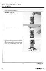
Page 62: ...RCT150A Operator Service Maintenance Manual 62 Troubleshoot ...

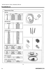
Page 63: ...RCT150A Operator Service Maintenance Manual 800 392 2686 63 Troubleshoot ...

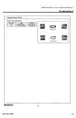
Page 64: ...RCT150A Operator Service Maintenance Manual 64 Troubleshoot ...

Page 65: ...RCT150A Operator Service Maintenance Manual 800 392 2686 65 Troubleshoot ...

Page 66: ...RCT150A Operator Service Maintenance Manual 66 Troubleshoot ...

Page 67: ...RCT150A Operator Service Maintenance Manual 800 392 2686 67 Troubleshoot ...

Page 68: ...RCT150A Operator Service Maintenance Manual 68 Troubleshoot ...

Page 69: ...RCT150A Operator Service Maintenance Manual 800 392 2686 69 Troubleshoot ...

Page 70: ...RCT150A Operator Service Maintenance Manual 70 Troubleshoot ...

Page 71: ...RCT150A Operator Service Maintenance Manual 800 392 2686 71 Troubleshoot ...

Page 72: ...RCT150A Operator Service Maintenance Manual 72 Troubleshoot ...

Page 73: ...RCT150A Operator Service Maintenance Manual 800 392 2686 73 Troubleshoot ...

Page 74: ...r machine Conoco Phillips MegaFlow AW HVI 46 Viscosity 7 7 cSt 100 C 46 cSt 40 C Pour Point 45 C 49 F Shell Tellus T 46 new name Tellus S2 V46 Viscosity 7 95 cSt 100 C 45 9 cSt 40 C Pour Point 42 C 43 F Mobil DTE 15M Viscosity 7 8 cSt 100 C 46 cSt 40 C Pour Point 42 C 43 F Exxon Univis N 46 Viscosity 8 2 cSt 100 C 46 cSt 40 C Pour Point 48 C 54 F Pennzoil Pennzbell AWX MV 46 Viscosity 8 8 cSt 100 ...

Page 75: ... C 4 F to 212 F Note for extreme cold temperature areas a No 0 grade grease may be used Before lubricating make sure all grease fittings and the nozzle of the grease gun is clean Cold Weather Lubricants Before attempting to start the engine make sure that the oil in the engine the transmission and the hydraulic system are fluid enough to flow Check the oil by removing the dipsticks If the oil will...

Page 76: ...34 227045 with bitterant 34 F 50 mix 62 F 60 mix Coolant Maintenance Maintain freeze point between 15 F and 62 F A 50 mixture has a freeze point of 34 F refer to freeze point above Use commercially available test strips for both nitrate and molybdate Maintain nitrate levels between 800ppm and 2300ppm Check levels of nitrate and molybdate every 250 hrs Add SCA s based upon the engine OEM recommenda...

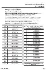
Page 77: ...ntenance Section SAE Metric Bolt Torque Requirements SAE GRADE 8 TORQUE DRY OR LOCTITE 1 4 12 2 LB FT 5 16 26 2 LB FT 3 8 46 2 LB FT 7 16 75 5 LB FT 1 2 115 5 LB FT 9 16 160 5 LB FT 5 8 225 10 LB FT 3 4 400 20 LB FT 7 8 650 25 LB FT 1 975 25 LB FT 1 1 8 1350 25 LB FT 1 1 4 1950 25 LB FT 1 3 8 2550 25 LB FT 1 1 2 3350 50 LB FT METRIC CLASS 10 9 DRY OR LOCTITE M6 12 2 LB FT M8 30 3 LB FT M10 60 3 LB...

Page 78: ...contaminato 5 5 Connection of the hydraulic system 1 Clean hoses thoroughly prior to connection and remove any internal obstructions Prevent any foreign particles from getting into the hoses by removing the plastic caps only at the time of the assembly After hoses are connected to the motor flow the hydraulic circuit and filter the oil from all the particles that may have contamined it 2 Pulire la...

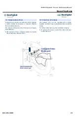
Page 79: ...onamento Per ulteriori informazioni fare riferimento al disegno di installazione 1 Per azionare il freno collegare il tubo di comando freno alla porta comando freno 5 6 Connection of the brake The gearbox drive can be supplied with a safety negative multidisc brake hydraulically driven parking brake For further information see the installation drawing 1 To operate the brake connect the brake pilot...

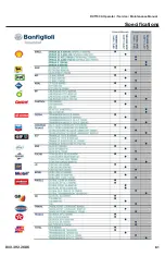
Page 80: ...olio consigliati Durante l esercizio e solo per brevi momenti l olio può raggiungere ma non superare la temperatura di 85 90 C intermittente se non diversamente indicato nel disegno di installazione In the following table the most common brands of lubricant and the types recommended are shown During the operation the oil temperature must not exceed 85 90 C intermittent if not otherwise indicated o...

Page 81: ...RCT150A Operator Service Maintenance Manual 800 392 2686 81 Specifications REV 0 1 22 39 MAN_serie600_IS doc ...

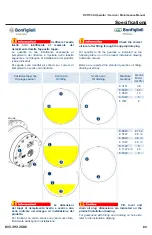
Page 82: ...s 1A 1B 5 Run the gearmotor after a few minutes stop and check the oil level 6 If necessary refill with lubricant oil For further information see the installation drawing Tighten the plugs by a torque wrench at a torque shown on the table in the end of this manual 6 3 Scarico e sostituzione olio 1 Con l asse del riduttore in orizzontale ruotare il corpo fino a che il tappo di scarico 1B si trovi i...

Page 83: ...ing table or on the product installation drawing Indicative values Belove are reported the standard gearbox oil filling draining sketches Posizione tappi olio Oil plugs position Carico olio Oil filling Scarico olio Oil draining Riduttore Gearbox Qt olio Oil qt l 10 dwqdq 6 01 R 0 8 6 03 W 0 7 6 05 W 1 3 6 13 W 5 6 15W 6 6 06 W 2 1 2 6 07 W 2 5 2 6 09 W 3 5 3 6 10 W 4 5 3 6 11 W 5 6 11 W 2 3 4 5 6 ...

Page 84: ...idazione ed accelerano il deterioramento dell olio idraulico Osservare quindi le seguenti precauzioni 1 La temperatura dell olio idraulico in esercizio continuo di lavoro si mantenga in un campo fra i 25 C 90 C 2 La temperatura di messa in funzione deve essere possibilmente al di sopra di 20 C 3 Durante l esercizio e solo per brevi momenti l olio può raggiungere ma non superare la temperatura di 9...

Page 85: ...questo primo rodaggio eseguire le operazioni di seguito indicate 8 Controllare che non vi siano perdite olio In caso contrario provvedere alla loro eliminazione 9 Controllare il livello dell olio lubrificante del motoriduttore 10 Durante il primo avviamento causa l eventuale presenza di aria l apertura del freno potrebbe risultare ritardata Ripetere alcune volte il comando di apertura e chiusura d...

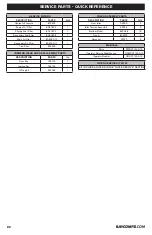
Page 86: ... Filter 803903 TRACK ASSEMBLY PARTS DESCRIPTION PART Qty Front Idler 33293 2 Idler Tension Assembly 32326 2 Bottom Roller 803068 16 Track 803072 2 Sprocket 32740 2 MANUALS Parts PMRCT150A 19 Operator Service Maintenance OSMRCT150A 19 Operator Booklet OBRCT150A 19 COMMON WEAR AND REPLACEMENT PARTS DESCRIPTION PART Qty Door Key 762015 1 Ignition Key 764136 1 O Ring Kit 800186 1 FILTER SERVICE KIT 40...

Page 87: ...e place at which warranty work is performed 3 Any product that has been altered or modified in ways not approved by Rayco 4 Depreciation or damage caused by normal wear lack of reasonable and proper maintenance failure to follow operating instructions misuse lack of proper protection during storage or accident D Unapproved Service or Modification Rayco is relieved of its obligation under this warr...

Page 88: ...hink Smart Think Safe We care about your safety When operating your RAYCO machinery always wear an ap proved helmet complete with ear muffs face shield and the proper eye wear Never operate under the influence of alcohol or drugs Know your RAYCO read and understand your owner s manual cover to cover RAYCO Manufacturing Inc retains the right to make changes in design and specifications engineering ...

Reviews: