background image

RG13II Operation • Maintenance • Parts 

18

Safety 

  b. Inspect and maintain the seat suspension and 

adjustment mechanisms.

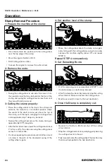
5. Perform the following operations smoothly.
  a. Steer
  b. Brake
  c. Accelerate
  d. Shift the gears
6. Move the attachments smoothly.
7. Adjust the machine speed and the route in order to 

minimize the vibration level.

  a. Drive around obstacles and rough terrain.
  b. Slow down when it is necessary to go over rough 

terrain.

8. Minimize vibrations for a long work cycle or a long travel 

distance.

  a. Haul the machines between workplaces.

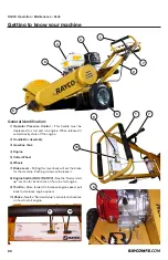
Guards (Operator Protection)

There are different types of guards that are used to protect 
the operator.  The machine and the machine application 
determines the type of guard that should be used. 
A daily inspection of the guards is required in order to check 
for structures that are bent, cracked or loose.  Never operate 
a machine with a damaged structure.
The operator becomes exposed to a hazardous situation if the 
machine is used improperly or if poor operating techniques 
are used.  This situation can occur even though a machine is 
equipment with an appropriate protective guard.  

Other Guards (If Equipped)

Protection from flying object and/or falling objects is required 
for special applications.  Logging applications and demolition 
applications are two examples that require special protection.
A front guard needs to be installed when a work tool that 
creates flying objects is used.  Mesh front guards that are 
approved by Rayco or polycarbonate front guards that are 
approved by Rayco are available for machines with a cab or 
an open canopy.  On machines that are equipped with cabs, 
the windshield should also be closed.  Safety glasses are 
recommended when flying hazards exist for machines with 
cabs and machines with open canopies.
If the work material extends above the cab, top guards and 
front guards should be used.  
Additional guards may be required for specific applications 
or work tools.  The Operation and Maintenance Manual 
for your machine or your work tool will provide specific 

requirements for the guards.  Consult your Rayco dealer for 
additional information.

Precautions for Welding on FRAME 

with ENGINE/MACHINE Electronic 

Control Unit (ECU)

Important: ALWAYS disconnect Electronic Control Unit (ECU) 
connectors and engine control system-to-machine ground 
before welding on engine or machine.
High currents or electrostatic discharge in electronic 
components from welding may cause permanent damage

Safety Decals

The safety decals located on this machine contain useful 
and important information which will help you to operate 
your machine safely. The complete decal kit and location of 
each decal is given in the “Parts” manual. For your protection, 
familiarize yourself with each label until you completely 
understand the warning intended. Do not violate any such 
warnings!
Keep all decals in place and in good condition:

•  Use soap and water to keep decals clean. DO NOT 

use mineral spirits, abrasive cleaners or other similar 

cleaners which will damage the decals.

•  Replace any damaged or missing decals. Before 

attaching decals, the surface temperature of the metal 

must be at least 40 degrees. The metal should also be 

clean and dry before attaching the decal.

•  If a machine component to which a decal is attached is 

replaced, be sure to replace the decal as well.

•  Replacement decals may be purchased from Rayco Mfg 

or your Rayco dealer.

LOCK-Out / Tag-Out Guidelines

Always practice lock out tag out procedures when working 
on this machine.
Locking and tagging out equipment safeguards those working 
on the equipment from being injured by its unexpected 
energized or releasing stored energy. This section summarizes 
the applicable requirements for lockout/ tag out procedures, 
and its intent to comply with OSHA regulations.

Lock Out Procedure

•  All affected persons are to be notified that the equipment 

will be off and locked out.

•  All energy sources for the equipment should be identified.
•  The equipment shall be shut off or otherwise deenergized, 

being careful to de-energize all energy sources. This 

includes all valves, switches, breakers, or other controls 

Summary of Contents for RG13II

Page 1: ...RG13II OPERATOR MAINTENANCE PARTS MANUAL COPYRIGHT 2014 RAYCO ALL RIGHTS RESERVED PRINTED IN USA INDEX OSBPRG13II 14 ...

Page 2: ...derstandallinstructionsbefore attempting to operate this machine This manual should be readily available for reference at all times Additional copies of this manual may be purchased from Rayco This Rayco machine was designed and manufactured by RaycoManufacturing Inc Wooster Ohio Duetocontinuous improvements Rayco reserves the right to make changes in engineering design and specifications or disco...

Page 3: ...RG13II Operation Maintenance Parts 800 392 2686 3 Table of Contents TABLE OF CONTENTS Forward 4 Safety 8 Operation 22 Maintenance 26 Specifications 50 Warranty 51 ...

Page 4: ... Operation The operation section is a reference for the new operator and a refresher for the experienced operator This section includesadiscussionofgauges switches machinecontrols attachment controls transportation and towing information Photographs and illustrations guide the operator through correct procedures of checking starting operating and stopping the machine Operating techniques outlined ...

Page 5: ...r death Never put maintenance fluids into glass containers Drain all liquids into a suitable container Obey all local regulations for the disposal of liquids Use all cleaning solutions with care Report all necessary repairs Do not allow unauthorized personnel on the equipment Unless you are instructed otherwise perform maintenance with the equipment in the servicing position Refer to Operation and...

Page 6: ...for the number of produced 01 Two digit month 01 Jan 02 Feb etc 14 Two digit year 14 2014 15 2015 etc It is attached to the machine at the location shown For ready reference record it in the boxes provided on the inside front cover of this manual For reference on communication regarding the engine record its model and serial numbers also in the boxes provided on the inside front cover of this manu...

Page 7: ...on Identification Numbers Model Number Serial Number Machine Engine Implement Implement Dealer Information Name Address Dealer Contact Phone Number Hours Sales Parts Service Serial number is located as shown Use the below table to record identification numbers and dealer information ...

Page 8: ... not specifically recommended by Rayco you must use it only if you have accurately evaluated it and found that it threatens no one s safety You should also ensure that the product will not be damaged or made unsafe by the operation lubrication maintenance or repair procedures that you choose The procedures described in this Safety section may not be fully explained here but a more complete explana...

Page 9: ...ust conform to ANSI Z89 1 and DO NOT wear under chin strapping while operating or within the operation area of the Horizontal Grinder Eyeprotection mustconformtoANSIZ87 1andbethewrap aroundstyle Alwaysweartheeyeprotectionwhenoperating or working within the operational area of the machine Hearing Protection Plug type ear protection or full ear coverage devices muff type shall be worn at all times w...

Page 10: ...hat is under pressure can penetrate body tissue Fluid penetration can cause serious injury and possible death A pin hole leak can cause sever injury If fluid is injected into your skin you must get treatment immediately Seek treatment from a doctor that is familiar with this type of injury Containing Fluid Spillage Caremustbetakeninordertoensurethefluidsarecontained during performance of inspectio...

Page 11: ...ngine Unexpectedmachinemovementcouldresult Wheneverthereareequipmentcontrollinkages theclearance in the linkage area will change with the movement of the equipment or the machine Stay clear of areas that may have a sudden change in clearance with machine movement or equipment movement Avoid contact with the rotating feed wheel cutter wheel and rotor Always shut off the engine and wait for all movi...

Page 12: ...iller cap is cool before removing the filler cap The filler cap must be cool enough to touch with a bare hand Removethefillercapslowlyinordertorelievepressure Cooling system conditioner contains alkali Alkali can cause personal injury Do not allow alkali to contact the skin the eyes or the mouth Oils Hot oil and hot components can cause personal injury Do not allow hot oil to contact the skin Also...

Page 13: ... flammable and or explosive Repair such components in a well ventilated area away from open flames or sparks Inspect all lines and hoses for wear or for deterioration The hoses must be properly routed The lines and the hoses must have adequate support and secure clamps Tighten all connections to the recommended torque Leaks can cause fires Usecautionwhenyouarerefuelingamachine Donotsmoke while you...

Page 14: ... should never attempt to operate the machine If you are on the ground during an electrical storm stay away from the vicinity of the machine While Operating the Machine All personnel using this Machine must be trained in the operation safety and maintenance repair procedures Careless use of this Equipment could result in serious injury or even death ALLPROCEDURESINTHESAFETYANDOPERATION SECTIONS OF ...

Page 15: ...o the control bar may result in personal injury or death NEVER remove the cap from the hydraulic tank or reservoir while the machine is running Hot oil under pressure will cause injury Relieve hydraulic system pressure before repairing or adjusting fittings hoses tubing or other system components Before Starting Engine Start the engine only from the operator compartment Never short across the star...

Page 16: ...e edge of a cliff an excavation or an overhang If the machine begins to sideslip downward on a grade immediately turn the machine downhill Avoid any conditions that can lead to tipping the machine The machine can tip when you work on hills on banks and on slopes Also the machine can tip when you cross ditches ridges or other unexpected obstacles Avoidoperatingthemachineacrosstheslope Whenpossible ...

Page 17: ...achine and on the work tool Always wear protective glasses Always wear the protective equipment that is recommended in the work tool s operation manual Wearanyotherprotectiveequipmentthatisrequired for the operating environment To prevent personnel from being struck by flying objects ensure that all personnel are out of the work area While you are performing any maintenance any testing or any adju...

Page 18: ...Operation and Maintenance Manual for your machine or your work tool will provide specific requirements for the guards Consult your Rayco dealer for additional information Precautions for Welding on FRAME with ENGINE MACHINE Electronic Control Unit ECU Important ALWAYSdisconnectElectronicControlUnit ECU connectors and engine control system to machine ground before welding on engine or machine High ...

Page 19: ...ase block Removal Procedure Lockout tag out equipment must be removed by the worker who placed it Before the removal of a lockout tag out the following must be completed 1 Removal of all non essential items 2 Check to see that all workers and bystanders are located in a safe position 3 Inform all affected personnel Ifaworkerwhoappliedthelockout tagoutisnotpresent and his supervisor deems it necess...

Page 20: ...ly 3 Gasoline Tank 4 Engine 5 Cutter Wheel 6 Wheels 7 Brake Lever Pulling this lever back will set the brake for the machine Pushing it down will release it 8 Engine Switch RUN ON OFF Seethe Normalstart up section for instructions on how to start engine 9 Throttle Move forward to increase engine speed pull back to decrease engine speed 10 Choke Seethe Normalstartup sectionforinstructions on how to...

Page 21: ...pplicable before operating the machine Starting the Engine Understand and heed to the Safety section of this manual in its entirety before proceeding 1 Lockthetravelwheelbypullingthebrakeleverfullyback 2 Make sure the engine switch is ON 3 Make sure the throttle is in SLOW position 4 If the engine is cold move the choke lever to the closed position 5 Depress the operator presence lever 6 Raise the...

Page 22: ...everyone in the vicinity is aware of the DANGER ZONE associated with this machine Everyone must avoid the DANGER ZONE at all times when the machine is in operation 10 For safety local or state codes or job site operating directives may require a greater distance from obstacles 11 Keep eye contact with the cutting wheel at all times that it is rotating 12 Use only the front lower portion of the cut...

Page 23: ...ove all loose pieces of wood stones wire and other debris from the work area before beginning stump removal BEFORE OPERATING PLEASE CAREFULLY REVIEW THE SAFETY SECTION FOR VITAL INFORMATION RELATED TO OPERATING THIS POWERFUL MACHINE NOTICE Wind direction should be considered as it influences the direction that dust and wood chips will be directed NOTICE Never operate the machine after dark Night t...

Page 24: ...ep bite After the first bite is taken lower the cutting wheel about 2 while is off to the side and swing the cutting wheel across for another bite Continuerepeatingthisprocedureuntilalloftheamount of stump in the path of the downward swing of the cutting wheel is gone 4 Cut another level of the stump Raise the cutting wheel above the stump once again and starting with the cutting wheel swung to on...

Page 25: ...ged Store it away from wherever an open flame or sparks might occur Information on preparing the engine for storage is contained in the Storage section of the Honda Engine Operation Manual shipped with this machine Check your machine for any worn or broken parts at this time By ordering and installing replacement parts now you can avoid unnecessary delays when you remove the machine from storage R...

Page 26: ...Know the appropriate work site hand signals and the per sonnel that are authorized to give the hand signals Accept hand signals from one person only Do not smoke when you service an air conditioner Also do not smoke if refrigerant gas may be present Inhaling the fumes that are released from a flame that contact air conditioner refrigerant can cause bodily harm or death In haling gas from air condi...

Page 27: ...RG13II Operation Maintenance Parts 800 392 2686 27 Maintenance Maintenance Log Date of Service Machine Hours Description of Service Maintenance Notes ...

Page 28: ...X X X X Cutter Wheel Bearings Lubricate X X X X X X X Air Filter Check X X X X X X X Air Filter Clean X X X X Air Filter Replace X Walk Around Inspection X X X X X X X Engine Leaks Check X X Engine Oil Change X X X Engine Mounts Check X X X X X V Belt Tension Check X X X X X Brake Adjust X X Brake Lining Check X Tire Condition Check 2 years Spark Plug Clean Re adjust X X Spark Plug Replace X Sedim...

Page 29: ...iment cup in nonflammable solvent and dry it thoroughly 4 Place o ring in the fuel valve and install the sediment cup Tighten the sediment cup securely 5 Open the throttle engine fuel valve tot he on position and check for leakage FollowthedirectionsfoundintheHondaEngineOperation Manual Fuel Tank and Strainer Clean FollowthedirectionsfoundintheHondaEngineOperation Manual Engine Oil Level Check The...

Page 30: ...chine warranty Rayco s cutting tools cutting wheels and mower rotors are specifically designed to provide optimum performance in many ways The use of non Raycopartswillcompromisethisoptimumperformance Safety Rayco s cutting tools are always attached with at least two fasteners This redundant fastening system is farsaferthanthosesystemsemployingonlyonefastener Rayco s cutting tools are also more vi...

Page 31: ...ght and angled teeth should be staggered as shown in the drawing 6 When using Rayco brand square shanked teeth set the extreme edge of each tooth 1 away from the edge of the pocket 7 WhenusingRaycoSUPERTEETH becauseofonepiece construction no pre setting of the tooth is required 8 Make sure teeth are placed in coordination with wheel rotation 9 After setting each tooth pair tighten the socket head ...

Page 32: ...element Tap the filter element several times on a hard surface to remove dirt or blow compressedair 10 30psimax throughthefilterelement from the inside Never try to brush dirt brushing will force dirt into the fibers b Foam air filter element Clean in warm soapy water rinse and allow to dry 6 Remove the 3 pan head screws from the pre cleaner cap then remove the cyclone housing and air guide Wash t...

Page 33: ... Spark Plug Replace FollowthedirectionsfoundintheHondaEngineOperation Manual Idle Speed Check FollowthedirectionsfoundintheHondaEngineOperation Manual Valve Clearance Check and Adjust FollowthedirectionsfoundintheHondaEngineOperation Manual Tire Condition Inspect Inspect tires and wheels for wear and damage BEFORE BEGINNING TO CHECK OR ADJUST THE BELT SHUTDOWN THE MACHINE ENSURE THAT ALL MOVING PA...

Page 34: ...URTAIN BELT GUARD BUF FER 25 4 761581 BEARING WHEEL 26 2 10438 PLATE WELD BACK UP ENG 27 1 10389 BELT GUARD WELD 28 1 761585 BRAKE MECHANISM 29 2 761779 COLLAR CLAMP 3 4 30 1 10795 WHEEL WELD BRAKE 31 1 762266 2 INNER RIM HALF 32 1 762266 3 INNER RIM HALF 33 1 10819 CURTAIN SIDE 34 1 10821 CURTAIN SIDE GUARD 35 1 10823 CURTAIN BACK 36 1 10419 CABLE BRAKE 37 1 730051 CLAMP VINYL COVERED 5 8 38 1 75...

Page 35: ...RG13II Operation Maintenance Parts 800 392 2686 35 Main Assembly 17 5 27 37 38 56 57 23 16 9 15 17 5 27 37 38 56 57 23 16 9 15 5 27 37 38 56 57 23 16 9 15 27 14 10 18 37 38 56 57 ...

Page 36: ...RG13II Operation Maintenance Parts 36 Main Assembly 18 36 39 35 32 19 47 34 6 33 41 44 54 4 42 43 2 30 31 29 7 13 27 12 35 1 10 48 18 11 1 3 52 36 27 38 22 39 55 8 15 49 50 51 21 ...

Page 37: ...RG13II Operation Maintenance Parts 800 392 2686 37 Main Assembly 24 7 12 43 47 28 25 30 46 52 53 36 27 38 22 37 42 45 35 48 39 20 29 1 19 2 13 17 26 38 44 41 54 4 14 6 33 55 8 15 49 50 51 21 ...

Page 38: ...RG13II Operation Maintenance Parts 38 Main Assembly 17 5 26 33 34 52 53 22 16 9 15 17 5 26 33 34 52 53 22 16 9 15 26 14 10 18 33 52 53 ...

Page 39: ...RG13II Operation Maintenance Parts 800 392 2686 39 Main Assembly 18 32 35 1 31 19 43 30 6 29 37 40 50 4 38 39 2 29 7 13 26 12 31 1 10 44 32 11 1 3 48 56 ...

Page 40: ...RG13II Operation Maintenance Parts 40 39017 Frame Assembly 4 15 3 4 9 20 5 4 16 13 23 8 ...

Page 41: ... BACK 8 1 11159 PIN HINGE 9 1 11450 SPACER HUB 10 1 12111 SIDE BRAKE CURTAIN RETAIN 11 1 12112 SIDE U CURTAIN RETAIN 12 1 12114 SIDE CURTAIN RETAIN 13 1 36063 WHEEL BRAKE WELD RG13 II 14 24 722103 BOLT HEX 1 4 20 X 3 4 GR8 15 4 722307 BOLT HEX 3 8 16 X 2 16 2 726203 WASHER FLAT 3 16 USS PL 17 24 726607 FENDER WASHER 18 1 726803 WASHER FLAT 3 4 14GA 19 2 761581 BEARING WHEEL 20 1 761585 BRAKE MECHA...

Page 42: ...1 1 1521 CURTAIN 2 1 1522 CURTIAN SIDE 3 2 1524 CURTAIN 4 1 1525 CURTAIN BELT GUARD BUFFER 5 1 1526 CURTAIN 6 1 5132 CURTAIN SIDE 7 1 6172 REAR CHIP GUARD WELD 8 1 6173 CURTAIN REAR 9 2 12397 BRKT MTG CURTAIN WELD 10 21 722103 BOLT HEX 1 4 20 X 3 4 GR8 11 8 722110 BOLT WHIZ 1 4 20 X 3 4 12 21 726607 FENDER WASHER 13 1 REF WELDMENT MAIN FRAME ...

Page 43: ...0 X 3 4 GR8 4 2 722104 BOLT HEX 1 4 20 X 1 GR8 5 1 722310 BOLT TAP 3 8 16 X 4 GR2 6 4 722333 BOLT CAR 3 8 16 X 2 7 1 724102 NUT HEX 10 24 8 4 724301 NUT HEX 3 8 16 GR8 9 2 726101 WASHER FLAT 1 4 USS 10 2 726102 WASHER LOCK 1 4 11 1 726103 WASHER LOCK 10 12 1 726203 WASHER FLAT 3 16 USS PL 13 3 726301 WASHER FLAT 3 8 USS 14 4 726302 WASHER LOCK 3 8 15 1 730025 CLAMP VINYL COVERED 1 16 1 738204 CAP ...

Page 44: ...E 2 1 1505 PIN BRAKE W SET SCREW 3 1 1506 LOCK COLLAR 4 1 610000 BRAKE STRAP 5 1 610005 LEVER BRAKE 6 1 610035 SPRING BRAKE RETURN 7 2 722204 BOLT HEX 5 16 18 X 2 3 4 GR8 8 2 724201 NUT HEX 5 16 18 GR8 9 6 726201 WASHER FLAT 5 16 10 2 726202 WASHER LOCK 5 16 PLATED 11 2 730009 SCREW SET 1 4 COUNTER PT 12 1 736067 CABLE BRAKE RG12 20 ...

Page 45: ...E ACTUATOR 11 4 750456 SCREW 10 24 X1 2 HH MACH 12 1 630010 SWITCH DEADMAN 13 1 10431 SPRING TORSION 14 2 630013 NUT PUSH 1 4 15 2 7013 04 SPACER 7 16 OD x 0 272 ID 16 2 728014 PIN CLEVIS 1 4 X 2 17 1 610005 LEVER BRAKE 18 2 722204 BOLT HEX 5 16 18 X 2 3 4 GR8 19 8 726201 WASHER FLAT 5 16 20 1 2541 09 1 2 OD x 14 GA WALL TUBING 21 2 726202 WASHER LOCK 5 16 PLATED 22 2 724201 NUT HEX 5 16 18 GR8 23...

Page 46: ...L RAYCO WORDMARK 10 H 9 1 30224 DECAL MADE IN USA 2013 LOGO 10 1 30255 DECAL CONSOLE RG13 II 11 1 39748 DECAL LEAD AND DIESEL WARNING 12 1 640055 DECAL CAUTION REVOLVE CW 13 1 640056 DECAL WARNING 1 DO NOT 14 1 640058 DECAL EXCESSIVE BELT TEN SION 15 1 732008 DECAL CAUTION EAR EYE 16 1 732009 DECAL CAUTION OVER TIGHTENING 17 1 732014 DECAL TOOTH BOLT TORQUE 18 1 732018 DECAL DANGER ROTATING CW 19 ...

Page 47: ...heel thickness 3 8 95cm Bearings 2 1 3 cm pillow block with lip contact seals Speed 3 480 rpm w engine at 3 900 rpm Drive belts 2 section banded v belt Belt guard Electrically welded steel fully enclosed Cutter teeth 8 RAYCO SUPERTEETH Chip deflection Steel fabric impregnated rubber Clutch Centrifugal Additional safety features Steel guard operator presence engine shut down low oil pressure engine...

Page 48: ...LL PWR TYPE B RAYCO MFG INC CAD GENERATED DRAWING DO NOT MANUALLY UPDATE DWG NO HARNESS DEAD MANS SWITCH DATE SCALE FINISHED WEIGHT SHEET UNLESS OTHERWISE SPECIFIED DIMENSIONS ARE IN INCHES TOLERANCES ARE FRACTIONAL 1 32 00 010 000 005 ANGULAR 1 MATERIAL DO NOT SCALE DRAWINGS RG13II 40029 OF WOOSTER OHIO 10 10 18 1 2 0 000 1 1 THE INFORMATION CONTAINED IN THIS DRAWING IS THE SOLE PROPERTY OF RAYCO...

Page 49: ...RG13II Operation Maintenance Parts 800 392 2686 49 ...

Page 50: ...ickness 3 8 95cm Bearings 2 1 3 cm pillow block with lip contact seals Speed 3 480 rpm w engine at 3 900 rpm Drive belts 2 section banded v belt Belt guard Electrically welded steel fully enclosed Cutter teeth 8 RAYCO SUPERTEETH Chip deflection Steel fabric impregnated rubber Clutch Centrifugal Additional safety features Steel guard operator presence engine shut down low oil pressure engine shut d...

Page 51: ...he product to and from the place at which warranty work is performed 3 Any product that has been altered or modified in ways not approved by Rayco 4 Depreciation or damage caused by normal wear lack of reasonable and proper maintenance failure to follow operating instructions misuse lack of proper protection during storage or accident D Unapproved Service Modification Rayco is relieved of its obli...

Page 52: ...hink Safe We care about your safety When operating your RAYCO machinery always wear an ap proved helmet complete with ear muffs face shield and the proper eye wear Never operate under the influence of alcohol or drugs Know your RAYCO read and understand your owner s manual cover to cover RAYCO Manufacturing Inc retains the right to make changes in design and specifications engineering add or remov...

Reviews: