RG55R Operation • Service • Maintenance
800.392.2686
45
Maintenance
remove a clear “kerf” from the stump without the body
of the tooth ever contacting the stump. This concept
reduces drag, which maximizes the use of the machine’s
horsepower. This also reduces wear on the tooth body
and on the attachment hardware. Many of the other
cutting tool systems available today do not address this
important aspect of cutting.
• Cutting Tool Dimensions: Rayco’s stump cutting teeth
are carefully designed to have the proper size of carbide
tip. Carbide tips ultimately become dull, and using
large, oversized carbide tips will induce extreme impact
energies into the machine’s structure.
• Debris Retention: Rayco’s cutting tool patterns are
designed to minimize the retention of debris in between
the cutting tools. This debris can cause imbalance. This
debris can also become a dangerous projectile. Non-
Rayco cutting tools may retain more debris.
Changing Teeth
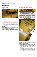
Remove the socket head bolts from the teeth. (Use the 1/2”
hex key provided with the machine.)
• Clean all dirt from the cutting wheel and teeth.
• Check the cutting wheel for cracks. Re place the wheel
if it is cracked.
• Carefully select and insert new cutting teeth, properly
positioning each tooth as shown in the diagram on the
next page.
• Bolt the teeth to the cutting wheel (but not tightly until
the pattern has been double-checked).
• After setting each tooth pair, tighten the socket head
bolts to 135 to 145 foot-pounds.
Replacement teeth are available from your Rayco dealer or
direct from Rayco. Refer to the Parts manual for part numbers
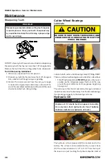
The Cutter Wheel (1) Rayco part# 35244 on the RG55 uses
6 different types of SuperTeeth as shown below:
2)Straight Tooth - Part# 3144T (threaded) Qty of 3
3)Angle-Out Tooth - Part# 2933T (threaded) Qty of 9.
4)Straight Tooth - Part# 3144C (countersunk) Qty of 3.
5)Angle-Out Tooth - Part# 2933C (countersunk) Qty of 9
BLOCK OR OTHERWISE SECURELY SUPPORT
THE CUTTING BOOM WHEN CHANGING
TEETH.
NOTICE
Read all of the following instructions before
beginning to change the cutting teeth.
NOTICE
The following illustrations represents the exact
location required for positioning each tooth. Please
follow the diagrams very closely for good cutting
wheel performance.
2
3
3
3
2
3
3
3
3
3
3
2
1
1
4
5
5
5
4
5
5
5
4
5
5
5
NOTICE
DO NOT hammer the tip of a tooth. Due to the
super hardness of the tooth, it is brittle and may
chip from such treatment.
Summary of Contents for RG55
Page 27: ...RG55R Operation Service Maintenance 800 392 2686 27 Operation ...
Page 58: ...RG55R Operation Service Maintenance 58 Hydraulic Schematic 805921 ...
Page 59: ...RG55R Operation Service Maintenance 800 392 2686 59 Hydraulic Schematic 805921 ...
Page 67: ...RG55R Operation Service Maintenance 800 392 2686 67 Specifications ...

