T415 Operation & Service Manual
88
Maintenance
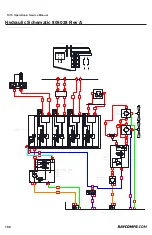
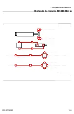
Hydraulic Circut Load Sense Pump
The Load Sense pump is mounted on the side of the engine
and supplies flow to both the fan circuit and control valve
blocks. The Sauer-Danfoss Series 45 Frame K pumps have a
single servo piston design with a cradle type swash plate set
in polymer-coated journal bearings. A bias spring and internal
forces increase swash plate angle. The servo piston decreases
swash plate angle. Nine reciprocating pistons displace fluid
from the pump inlet to the pump outlet as the cylinder block
rotates on the pump input shaft. The block spring holds the
piston slippers to the swash plate via the slipper retainer.
The cylinder block rides on a bimetal valve plate optimized
for high volumetric efficiency and low noise. Tapered
roller bearings support the input shaft and a viton lip-seal
protects against shaft leaks. An adjustable two spool (LS
and remote PC) control senses system pressure and load
pressure (LS controls). The control ports system pressure
to the servo piston, adjusting swash plate angle to control
pump output flow.
The pump receives fluid directly from the reservoir through
the inlet line. A screen in the inlet line protects the pump
from large contaminants. The pump outlet feeds directional
control valves such as PVG-32’s, hydraulic integrated circuits
(HIC), and other types of
control valves. The PVG valve directs pump flow to cylinders,
motors and other work functions. A heat exchanger cools the
fluid returning from the valve. A filter cleans the fluid before
it returns to the reservoir.
Flow in the circuit determines the speed of the actuators. The
position of the PVG valve determines the flow demand. A
hydraulic pressure signal (LS signal) communicates demand
to the pump control. The pump control monitors the pressure
differential between pump outlet and the LS signal, and
regulates servo pressure to control the swash plate angle.
Swash plate angle determines pump flow.
Actuator load determines system pressure. The pump control
monitors system pressure and will decrease the swash plate
angle to reduce flow if system pressure reaches the PC
setting. A secondary system relief valve in the PVG valve
acts as a back-up to control system pressure.
Pressure compensated controls:
The PC control maintains constant system pressure in the
hydraulic circuit by varying the output flow of the pump.
Used with a closed center control valve, the pump remains
in high pressure standby mode at the PC setting with zero
flow until the function is actuated. This condition is often
called a dead head condition. Once the closed center valve
is opened, the PC control senses the immediate drop in
system pressure and increases pump flow by increasing the
swash plate angle. The pump continues to increase flow until
system pressure reaches the PC setting. If system pressure
exceeds the PC setting, the PC control reduces the swash
plate angle to maintain system pressure by reducing flow.
The PC control continues to monitor system pressure and
changes swash plate angle to match the output flow with the
work function pressure requirements. If the demand for flow
exceeds the capacity of the pump, the PC control directs
the pump to maximum displacement. In this condition, actual
system pressure depends on
the actuator load. Each section includes control schematic
diagrams, setting ranges, and response /recovery times for
each control available. Response is the time (in milliseconds)
for the pump to reach zero displacement when commanded by
the control. Recovery is the time (in milliseconds) for the pump
to reach full displacement when commanded by the control.
Actual times can vary depending on application conditions.
Pressure compensated system
characteristics
• Constant pressure and variable flow
• High pressure standby mode when flow is not needed
• System flow adjusts to meet system requirements
• Single pump can provide flow to multiple work
functions
• Quick response to system flow and pressure
requirements Load sensing controls:
The LS control matches system requirements for both pressure
and flow in the circuit regardless of the working pressure.
Used with a closed center control valve, the pump remains
in low-pressure standby mode with zero flow until the valve
is opened. The LS setting determines standby pressure.
Most load sensing systems use parallel, closed center,
control valves with special porting that allows the highest
work function pressure (LS signal) to feed back to the LS
control. Margin pressure is the difference between system
pressure and the LS signal pressure. The LS control monitors
margin pressure to read system demand. A drop in margin
pressure means the system needs more flow. A rise in margin
pressure tells the LS control to decrease flow.
Load sensing system characteristics
• Variable pressure and flow
• Low pressure standby mode when flow is not needed
• System flow adjusted to meet system requirements
• Lower torque requirements during engine start-up
• Single pump can supply flow and regulate pressure
for multiple circuits
• Quick response to system flow and pressure
requirements


