34
Wuhan Raycus Fiber Laser Technologies Co., Ltd.
User Guide of RFL-C20000M-CE
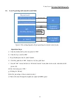
6.2. Laser Operating in External Control Mode
Raycus Laser
XP3(Serial Interface)
XP5(Ethernet Interface)
1
2
XP2
17
18
19
20
(Security Interface)
AC INPUT
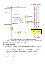
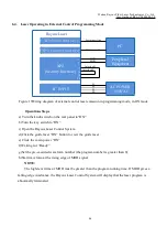
Figure 17the wiring diagram of laser operating in external control mode
Operations Steps
a
)
Turn the knobswitch on the rear panel to“ON”
b
)
Turn the key switch to“ON”
c
)
Open the Raycus Laser Control System
d
)
Click the guide laser “ON” button to view the guide laser
e
)
Turnoff “AD” mode and turn on “External Control” mode (this mode can be memorized after
power off)
f)Click the main power “ON”
g) Waiting for “Ready”
h) Set the percentage of laser emission power
i) Turn on the laser through the high level output by MOD signal
PC
AC POWER
~380VAC
L1
L2
PE
Interlock1
L3
Interlock2
Peripheral
Equipment
Serial port line
Ethernet cable
MOD+
MOD -

