21
Wuhan Raycus Fiber Laser Technologies Co., Ltd.
User Guide of RFL-C20000M-CE
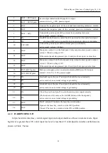
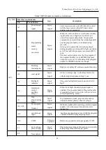
3
OUT
(
FET S pole
)
Laser output indication,MOS pipe D, S output;
current<0.1A, V
DS
<30V, passive signal.
4
OUT
(
FET D pole
)
5
OUT
Connect the negative pole of the external laser-emitting indicator, current
<
6
OUT
Connect the negative pole of the external power-on indicator, current
<
7
OUT
(
24V
)
Connect the positive pole of the external laser-emitting indicator;
active signal, current
<
400mA
8
IN
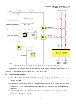
On REM mode, the main control board is powered on when pin-8 and pin-9
are closed;24V active contact Output,no external voltage or grounding.
9
IN
10
24V OUT
Connect the positive pole of the external power-on indicator;
active signal, current
<
400mA
11
OUT
Emergency output 1 on the front panel, relay output contact, passive contact,
current <100mA, voltage<30V;
If the current panel stop pressed, pin-11 and pin-14 are open, or else close.
14
OUT
12
OUT
Emergency output 2 on the front panel, relay output contact, passive contact,
current <100mA, voltage<30V;
If the current panel stop pressed, pin-12 and pin-13are open, or else close.
13
OUT
15
OUT(FET S pole)
Main power supply power on output indication,MOS pipe D, S output
current
<
0.1A,V
DS
<
30V, passive signal.
16
OUT(FET D pole)
17
IN
Interlock1 input, the pin-17 and pin-20 should be closed normally;
active contacts, no external voltage or grounding.
20
IN
18
IN
Interlock2 input, the pin- 18 and pin-19 should be closed normally;
active contacts, no external voltage or grounding.
19
IN
21
IN
Close the pin-21 and pin-22 to start the main power supplyremotely.
(The function is the same as the LASER button on the front panel.)
active contacts, no external voltage or grounding.
22
IN
23
OUT
Pin-23 and pin-24 indicate the laser key switch status:
Opened - the laser key switch is in the OFF position;
Closed - The laser key switch is in the ON or REM position.
24
OUT
4.4.2 HARDWIRING XP1
64 pin hard wire interface, control signal input and output interface of laser in remote mode. Input
high level is greater than 18V valid, input low level is less than 3V valid.Specific interface definitions are
shown in Table 7 below.


