27
Wuhan Raycus Fiber Laser Technologies Co., Ltd.
User Guide of RFL-C20000M-CE
380V/AC-50/60HZ
controller(k9)
contactor-k1
Internalemergencybutton
controller(k10)
XP2
C5
Leakdetection(Doubleloop)
C6
softwareemergencystop
Externalinterlock(Doubleloop)
LM1-LMn
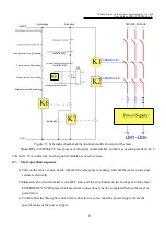
Figure 15 Schematic diagram of the internal electrical circuit of the laser
Note:
RFL-C20000M-CE laser power control part contactors K1 and K2 are used in parallel with 2
50A and 1 32A contactors, and 6 signal terminals are used in series.
4.7. Start operation sequence
a) Turn on the water cooler, check whether the water pipe is leaking, turn off the water cooler and
connect electrically.
b)Make sure the circuit breaker is in a OFF state and the stop button on the front panel of the laser
EMERGENCY STOP pressed; all electrical connections must be completed before the laser is
powered on.
c) Confirm that the three-phase electrical connection is correct and the power supply meets the
specifications of the power supply.
Laserdoorinterlock
(Reserved)
Fiberinterlock(Doubleloop)
contactor-k2
interlockloop
E-stoprelay
E-stoploop
+24VDC
OVDC
S4
start


