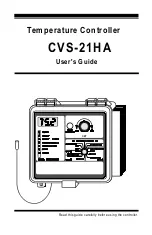
background image

U ser's G uide  

R ead this  guide carefully before  using  the controller.

C V S-21H A

Tem perature C on troller

SET

Summary of Contents for CVS-21HA

Page 1: ...User s Guide Read this guide carefully before using the controller CVS 21HA Temperature Controller SET ...

Page 2: ...temperatures 14 To reset the minimum and maximum temperatures 15 Parameter descriptions 15 Parameter factory settings 21 How to adjust the parameters 22 Parameter adjustment ranges 28 Alarms 29 How to lock the parameters 30 HOW THE CONTROLLER OPERATES 31 TROUBLESHOOTING 34 TECHNICAL SPECIFICATIONS 37 FOR CUSTOMER USE This controller has a serial number located on the side of the enclosure Please r...

Page 3: ...vides an automatic adjustment of the target room temperature over a given period of time A MINIMUM SPEED CURVE comprised of six different points provides an automatic adjustment of the first stage minimum speed over a given period of time A MINIMUM VENTILATION CYCLE allows you to operate the fans continuously or intermittently when ventilation is not required for a cooling purpose This reduces the...

Page 4: ...ore diversified control stategy When used in combination with a WR F 1A controller the CVS 21HA COORDINATES THE MOVEMENT OF THE AIR INLETS WITH THE OPERATION OF THE FANS This allows the air inlets to be adjusted correctly free of the influence of noncontrollable factors such as wind or air from adjoining rooms The controller generates an output signal that will activate any ALARM system in case of...

Page 5: ... guide Fuses on the input and outputs of the controller provide overload andovervoltageprotection Tofurtherprolongthelifeofthecontroller we recommend that you install an additional protection device on the supply circuit as well as an external relay on all ON OFF stages TheroomtemperaturewherethecontrollerisinstalledMUSTALWAYS REMAIN BETWEEN 32 ET 104 F 0 ET 40 C To avoid exposing the controller t...

Page 6: ...6 CVS 21HA rev 03 SET LOCATION OF THE CONTROLS Cover Internal circuit O N ...

Page 7: ...shes when the temperature curve is activated and the minimum speed curve is in operation DEFECTIVE PROBE PILOT LIGHT Turns on when a defective probe is detected ALARM PILOT LIGHT Turns on when the controller activates the alarm LOCKED PARAMETER PILOT LIGHT Turns on when the parameters are locked PARAMETER SELECTION KNOB Use this selection knob to select a parameter PUSH BUTTON Use this push button...

Page 8: ...PERATURE UNITS PROBE 2 PROBE 3 PROBE 4 ON OFF ON OFF ON OFF ON OFF ON OFF OPERATING MODE Locked parameters Unlocked parameters Degrees Celsius Degrees Fahrenheit Activated probe Deactivated probe Activated probe Deactivated probe 1 2 3 4 5 6 LOCKING THE PARAMETERS SWITCH POSITION 7 COOLING OR HEATING ON OFF Stage 3 used for heating Stage 3 used for cooling ...

Page 9: ...ter communication module If metallic cable holders are used to secure cables entering the enclosure usethegroundplateprovidedwiththecontroller Connect the ground wire to the ground stud on the plate Whenconnectingheatingunitstothecontroller itmaybenecessary to install a transformer in order to adapt the voltage to the heating units ALL WIRING MUST BE DONE BY AN AUTHORIZED ELECTRICIAN AND MUST COMP...

Page 10: ...he appropriate switch to ON Switch 3 activates terminal 2 Switch 4 activates terminal 3 Switch 5 activates terminal 4 FACTORY SETTING When the controller is shipped from the factory switches 3 4 and 5 are set to OFF probes are deactivated To connect the probes The controller is supplied with one probe connected to terminal 1 Up to three additional probes can be connected to the controller Use term...

Page 11: ...fective the word PR1 and the temperature measured by the probe will alternately appear on the display If the probe connected to terminal 1 supplied with the controller is defective the word PR1 and the letter P will alternately appear on the display For each additional probe connected to the controller Press the push button once again If the probe is not defective the word PR is the number of the ...

Page 12: ...ilable in the industry have been grouped into ten categories and the controller is programmed with a different motor curve for each of these categories Selecting an appropriate curve for each of the variable speed stages will ensure that the controller supplies the correct voltage to the fan motors To select a motor curve for stage 1 In the list of motors enclosed with this user s guide locate the...

Page 13: ...oller is shipped from the factory switch 2issettoOFF temperaturesaredisplayedindegreesFahrenheit The display flashes certain values and does not flash others The flashing indicates that the value on the display can be adjusted Values that are not flashing can not be adjusted VALUES FLASHING ON THE DISPLAY To select a motor curve for stage 2 Repeat the steps described for stage 1 this time setting ...

Page 14: ...cted to the controller Press the push button once again The word PR is thenumber oftheterminaltowhichtheprobeisconnected andthetemperature measured by the probe alternately appear on the display HOW TO VIEW AND RESET TEMPERATURES To view the minimum and maximum temperatures Set the parameter selection knob to ROOM TEMPERATURE The room temperature appears on the display Turn the adjustment knob clo...

Page 15: ...um temperature first appears flashing on the display After 10 seconds the display stops flashing and the room temperature again appears on the display indicating that the reset is completed When the minimum and maximum temperatures are reset their current valuesareerasedfrommemoryandthecontrollerbeginstostoreinmemory new values measured from that moment on NOTE To avoid resetting the minimum and m...

Page 16: ...s day number must be specified for each of the six points When the temperature curve is activated the controller adjusts the target room temperature every hour in a linear fashion between two consecutive points When the last point of the curve is reached the temperature curve becomes deactivated The controller maintains the last set point of the curve until the curve is reactivated or until a new ...

Page 17: ...e fans When the stage 1 fans operate according to the minimum ventilation cycle they run at mini mum speed This speed can be specified in two ways 1 With a single minimum speed When a single minimum speed is specified and the minimum speed curve is deactivated or the minimum speed curve is activated but not effectively in operation the stage 1 fans run at this speed 2 With a minimum speed curve Wh...

Page 18: ...minimum speed When the last point of the curve is reached the curve becomes deacti vated The controller maintains the last minimum speed of the curve until the curve is reactivated or until a new single minimum speed is specified The minimum speed curve and the temperature curve are related in the following ways The minimum speed curve can be activated only if the temperature curve is already acti...

Page 19: ...ns start to operate continuously and their speed varies according to the room temperature POINT 1 POINT 2 d5 d10 90 0 F 85 0 F 10 20 If you activated the temperature curve yesterday the current day number of the temperature curve is d6 Therefore if you activate the minimum speed curve today it will effectively be in operation only tomorrow when the current day number of the temperature curve reach...

Page 20: ...n stage 2 fans are turned off and opera tion of stage 1 fans is resumed at the appropriate speed De icing Cycle Time in minutes The stage 2 de icing cycle time is the time lapse between de icing operations De icing Time On in seconds The stage 2 de icing time on is the time stage 2 fans are turned on during de icing operations STAGE 3 EITHER CONSTANT SPEED FANS OR HEATING UNITS Differential F or C...

Page 21: ...th Minimum speed Bandwidth Differential Heater offset High offset STAGE 3 ALARM STAGE 2 STAGE 1 75 0 F 23 9 C deactivated 40 15 seconds 0 seconds 3 0 F 1 7 C 40 2 0 F 1 1 C 2 0 F 1 1 C 0 5 F 0 3 C 12 0 F 6 7 C PARAMETER FACTORY SETTINGS The controller is programmed at the factory with the settings shown below Keep the settings that are convenient for you and make changes where necessary These fact...

Page 22: ...point Set the parameter selection knob to SET POINT T CURVE The current set point appears flashing on the display Turn the adjustment knob to adjust the set point to the desired value To adjust the points of the temperature curve Set the parameter selection knob to SET POINT T CURVE The current set point appears flashing on the display NOTE If the power supply is cut off the parameter settings wil...

Page 23: ...t point for each unnec essary point of the curve 2 To reduce the risk of errors it is not permitted to specify decreasing day numbers it is not permitted to specify increasing temperature set points the highest day number is 99 the temperature variation can not exceed 3 F 1 6 C per day When the six points of the temperature curve have been specified the temperature curve must be activated for the ...

Page 24: ...d curve is activated as long as it is not effec tively in operation If the curve is in op eration deactivate the curve as de scribed below Deactivate the minimum speed curve as follows Set the parameter selection knob to MIN SPEED CURVE The current minimum speed appears flashing on the display Press the push button repeatedly until the word ON appears flashing on the display Turn the adjustment kn...

Page 25: ...mber appears flashing on the display Turn the adjustment knob to adjust the minimum speed to the desired value 1 All six points of the curve must be specified If you do not need six different points repeat your last minimum speed for each unnecessary point of the curve 2 To reduce the risk of errors it is not permitted to specify decreasing minimum speeds the minimum speed variation can not exceed...

Page 26: ...itive value Activate or deactivate the heater offset as follows Set the parameter selection knob to HEATER OFFSET The current heater offset appears flashing on the display STAGE 2 DE ICING To adjust de icing parameters n Set the parameter selection knob to STAGE 2 MIN SPEED and press the push button The current de icing cycle time is displayed alternating with the letters CyC n Turn the adjustment...

Page 27: ...g on the display Turn the adjustment knob clockwise one notch to activate the heater offset the word ON appears flashing on the display or counterclockwise to deactivate to heater offset the word OFF appears flashing on the display To adjust the stage 3 heater offset Set the parameter selection knob to HEATER OFFSET The current heater offset appears flashing on the display Turn the adjustment knob...

Page 28: ...00 seconds by increments of 15 seconds Time off STAGE 1 STAGE 2 STAGE 3 Minimum speed 10 to 100 of the full speed of the fans Bandwidth 0 5 and 20 0 F 0 3 and 11 1 C Heater offset activated deactivated 9 9 and 20 0 F 5 5 and 11 1 C 0 0 and 20 0 F 0 0 and 11 1 C 0 5 and 20 0 F 0 3 and 11 1 C Differential Temperature set point 40 0 and 99 9 F 40 0 and 37 7 C De icing Cycle Time 1 to 720 minutes De i...

Page 29: ...he low offset can be adjusted between 0 5o and 40 0o F 0 3 and 22 0 C LOW ALARM Thecontrolleractivatesthealarmwhentheambienttemperaturefalls below the value set point low offset To adjust alarm low offset Set selection knob to ALARM OFFSET HIGH The current high offset appears flashing on the display Usingadjustmentknob adjustthe offset to the desired value The high offset can be adjusted between 0...

Page 30: ...le set point if the temperature curve is deactivated and the single stage 1 minimum speed if the minimum speed curve is not effectively in operation All other parameter settings can not be changed To lock the parameters Set switch 1 to ON To unlock the parameters Set switch 1 to OFF FACTORY SETTING When the controller is shipped from the factory switch 1 is set to OFF the parameters are unlocked 1...

Page 31: ...s stop operating according to the minimum ventilation cycle and increase in speed as the room temperaturerises At POINT 2 the stage 1 fans reach full speed At POINT 3 the stage 2 fans start to run at minimum speed and increase in speed as the room temperature rises If the room temperature rises COOLING STAGE 3 TEMPERATURE SET POINT MINIMUM VENTILATION CYCLE ...

Page 32: ...At POINT 3 the stage 2 fans turn off At POINT 2 the stage 1 fans start to decrease in speed At POINT 1 the stage 1 fans reach minimum spped When room temperature set point the stage 1 fans operate ac cording to the minimum ventilation cycle at minimum speed At POINT 4 the stage 2 fans reach full speed At POINT 5 the stage 3 fans start to run ...

Page 33: ...emperatures above the set point When stage 3 is used for heating stages 1 and 2 operate as described for cooling However stage 3 operates at room temperatures below the set point as described hereafter HEATING If stage 3 is configured for heating stages 1 and 2 operate as described above see preceding diagram HEATING STAGE 3 At POINT 1 the stage 3 heating units turn on At POINT 2 the stage 3 heati...

Page 34: ...e the cable is firmly plugged in The controller has detected a defective probe Follow the procedure described in DEFEC TIVE PROBES page 11 to identify the defective probe Replace the defective probe The defective probe pilot light is on A variation in resistance is induced on the probe circuit Be sure the probes are dry Also move them away from drafts and from any source of radiant heating The dis...

Page 35: ...able is firmly plugged in The stage 1 or 2 minimum speed is too low Adjust the minimum speed to a higher value The fan motor is defective Connect the fan motor to an alternate power supply Repair the motor if it still is not operating The wiring is incorrect Correct the wiring The stage 1 fans run continuously at full speed The room temperature is above the set point Adjust the set point to the de...

Page 36: ...Be sure the cable is firmly plugged in The wiring is incorrect Correct the wiring In particular be sure two different lines are connected to each fan motor or heating unit line L1 at the controller s output should be combined with another line N for 115V or L2 for 230V to activate the fan motor or heating unit Also be sure the stage 3 COMMON is supplied by line L1 The fan motor or heating unit is ...

Page 37: ...w Stage 3 ON OFF output 115 230 VAC 60 Hz 30 VDC 6A FAN 10A RES heating or ventilation fuse F3 15A slow blow Alarm ON OFFoutput 115 230VAC 60Hz 30VDC 3A fuseF4 3Aslow blow Probes Low voltage 5V isolated from the supply Operating range 40 to120 F 40 to49 C Accuracy 1 8o F 1o C between41o and95o F 5o and35o C Enclosure ABS moisture and dust tight 115 230 VAC 18 8 60 Hz L1 same phases as Stage 1 and ...

Page 38: ...38 CVS 21HA rev 03 ...

Reviews: