background image

0049-3200-100 

ASTRO 25 Analog Modem II / ASTRO 25 IP Modem II Install Guide 

Rev. G   

37 


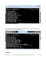
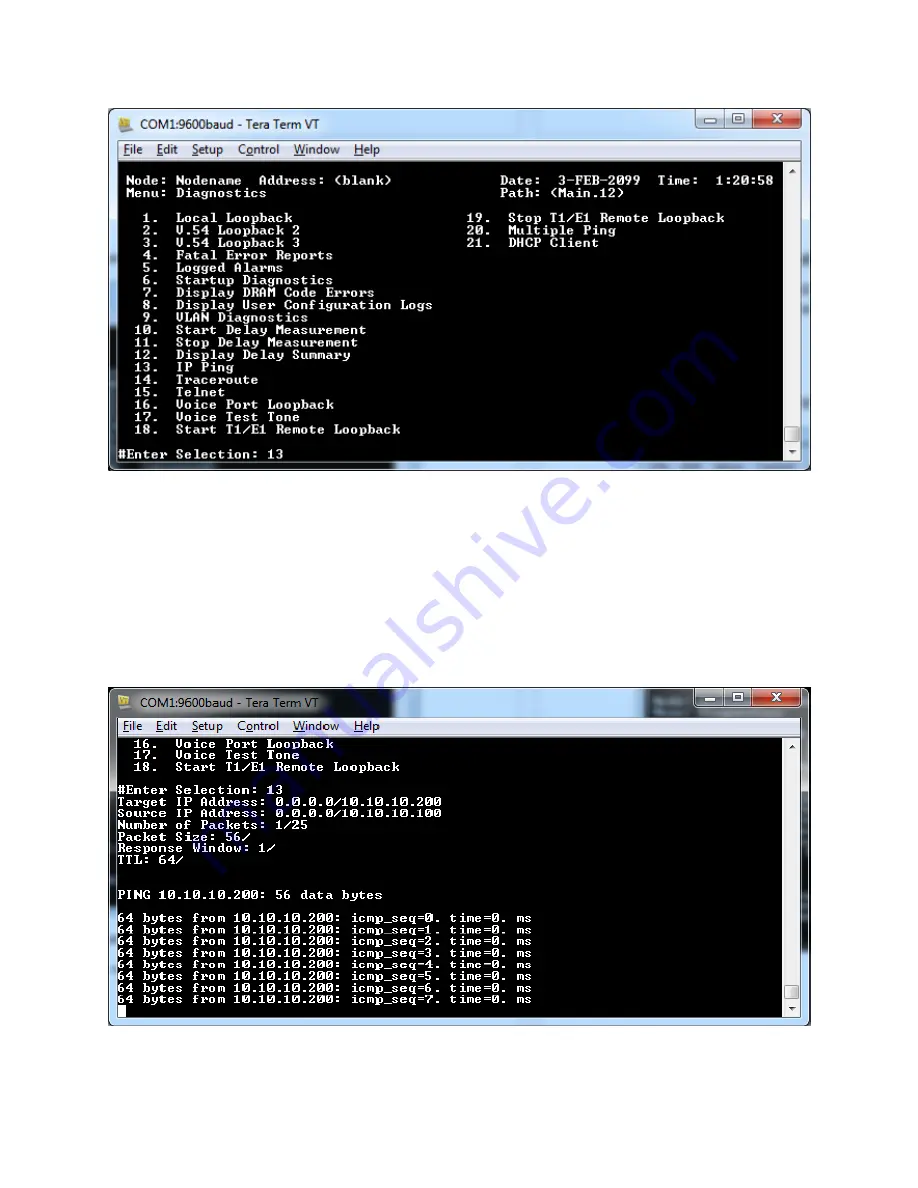
The Target IP will be the IP Address of the remote ASTRO 25 IP Modem II unit. 

The Source IP will be the IP Address of the local ASTRO 25 IP Modem II unit, the unit currently logged 
onto and performing the diagnostic test. 

Enter the number of packets to be transmitted. 

The remainder of the parameters can be left as default. After the last parameter is entered, the ping test 
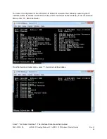
will commence. A successful ping test will show ICMP packets returned from the remote ASTRO 25 IP 
Modem II. 


An unsuccessful ping test will not show ICMP packets returned, instead ICMP packet loss. 

Summary of Contents for ASTRO 25 Analog Modem II

Page 1: ...0049 3200 100 ASTRO 25 Analog Modem II ASTRO 25 IP Modem II Install Guide Rev G 1 ASTRO 25 ANALOG MODEM II ASTRO 25 IP MODEM II GTR 8000 PORT EXPANDER Installation Guide ...

Page 2: ... without notice and does not represent a commitment on the part of Raymar Telenetics Raymar Telenetics assumes no responsibility for any inaccuracies that may be contained in this User s Guide Raymar Telenetics makes no commitment to update or keep current the information in this User s Guide and reserves the right to make changes to this User s Guide and or product without notice No part of this ...

Page 3: ...or different types of devices or services The USOC jack required for this unit is RJ11 RJ41S JM8 The telephone company may change technical operations or procedures affecting your equipment You will be notified of changes in advance to give you ample time to maintain uninterrupted telephone service If you experience trouble with this telephone equipment please contact Raymar Information Technology...

Page 4: ...t 1 lbs GTR 8000 Port Expander 2 lbs ASTRO 25 Analog Modem II ASTRO 25 IP Modem II Environmental Operating Temperature 32 to 98 F 0 to 40 C Storage Temperature 40 to 158 F 40 to 70 C Relative Humidity 5 to 90 Non condensing Power Requirements Input voltage 18 36VDC 90 265 VAC VDC when using 0057 3200 110 Input Current POWER OPTIONS ...

Page 5: ...re Parts Modem TEL 6209548100010 V 3600 RM UI MODEM Spare part only used with the ASTRO 25 Analog Modem II Bundle 0100 3200 100 Only DQTEL6209548100010 Cables 0057 3200 1EB CABLES EXTERNAL INTERCONNECT BUNDLE Replacement Bundle includes V 24 MIC Spkr 8 Wire interconnect cables DS005732001EB 0057 3200 100 CABLE SCSI INTERCONNECT 2 Replacement Item DS00573200100 0057 3200 110 CABLE DC POWER LUGS Rep...

Page 6: ...g any of the following methods Voice Calls We welcome your calls at 800 747 1522 Monday through Friday from 7 00 am to 5 00 pm Pacific Time Fax Number You can also send your requests for information to our 24 hour fax number 916 783 1952 E mail If you prefer you can send information requests to our 24 hour e mail address support Raymarinc com Website Our website contains valuable information about...

Page 7: ...g Modem II GTR 8000 Port Expander Applications 11 Section 3 02 ASTRO 25 IP Modem II Applications 12 Section 4 01 Cabling Your ASTRO 25 Analog Modem II ASTRO 25 IP Modem II Error Bookmark not defined 14 Section 4 02 Physical Layout 19Error Bookmark not defined Section 5 01 Installation Process 20 Section 5 02 Diagnostics 34 Section 6 01 APPENDIX 46 Section 6 02 Limited Warranty 46 a One Year Limite...

Page 8: ...ASTRO Modem MDC1200 feature TRC feature Section 1 02 APPLICATIONS The ASTRO 25 Analog Modem II the ASTRO 25 IP Modem II GTR 8000 Port Expander fulfills 3 roles Point to Point connectivity between the GTR 8000 and Astrotac Quantar base stations over a 4wire analog leased line network V 34 28 8Kbps Point to Point connectivity between the GTR 8000 and Astrotac Quantar base stations over an IP network...

Page 9: ...cting a location to install the ASTRO 25 Analog Modem II the ASTRO 25 IP Modem II GTR 8000 Port Expander choose a site that Is clean well lit and free from extremes of temperature humidity appreciable shock and vibration Is within seven feet of a power source that can furnish 90 265 VAC DC or 24 48 4 VDC at 3 5 amps Provides at least 36 inches of clearance at the front for operating and maintenanc...

Page 10: ...allation Section 2 05 INSTALLATION PROCEDURES Service personnel should be familiar with the complete installation procedure before installing the unit Section 3 01 ASTRO 25 Analog Modem II and GTR 8000 Port Expander Applications Figure A Leased Line Pt to Pt 8W V 24 8W V 24 Mic SCSI Spkr GTR 8000 with ASTRO TAC 3000 GTR 8000 Figure B 8W V 24 Mic SCSI Spkr GTR 8000 Port Expander GTR 8000 ...

Page 11: ...8 x 250 192 168 254 251 192 168 254 252 192 168 254 253 192 168 254 254 Management Station 192 168 254 250 Eth GTR 8000 with all other products ASTRO TAC 3000 Quantar DIU When multiple QUANTAR and GTR base stations are voted on the same ASTRO TAC comparator the ASTRO 25 Analog Modem II will be required for each leased link to the comparator Mixing the traditional QUANTAR ASTRO TAC interfaces with ...

Page 12: ...ure Our unique product solutions offer a wide range of solutions to meet any network requirements By utilizing existing IP infrastructure customers can eliminate monthly leased lines fees and improving the ROI on the new equipment investments Our ASTRO 25 IP Modem II solution provides easy access to traditional QUANTAR ASTRO TAC interfaces while providing connectivity for either V 24 or Hybrid con...

Page 13: ... ASTRO 25 Analog Modem II ASTRO 25 IP Modem II Install Guide Rev G 13 Large networks with complex layouts and multiple locations are easily supported using our Vanguard products offering network backup and failover ...

Page 14: ...GND Ve Prgm Port This port has an RJ45 connector Use the Prgm port for communicating with configuring monitoring and coldloading the node Pin Number Console Port Signal DCE 1 RTS Input 2 DTR Input 3 RXD Output 4 DCD Output 5 GND 6 TXD Input 7 DSR Output 8 CTS Output V 24 Pin Signal 1 RCLK 2 CD 3 TCLK 4 GND 5 RXD 6 TXD 7 CTS 8 RTS ...

Page 15: ...x Tx Rx Rx Rear 8 Wire Screw Connectors Left to Right Pin Signal 1 Line 3 2 Line 3 3 Line 4 4 Line 4 1 Line 1 2 Line 1 3 Line 2 4 Line 2 Ethernet Port Pin Signal 1 Transmit Positive 2 Transmit Negative 3 Receive Data Positive 4 Not Used 5 Not Used 6 Receive Data Negative 7 Not Used 8 Not Used ...

Page 16: ...hone Patch PL Strip 4 Phone Patch Monitor 23 Trunking Mute 15 Phone Patch RX Carrier Detect 12 Trunking TSTAT 7 22 Phone Patch Rx Audio Trunking Wideband Receive Audio 13 Trunking Tdata 2 Phone Patch PTT 24 trunking Control Channel Indicate 16 Ground 8 Phone Patch Inhibit 17 Ground 18 Ground 25 Trunking RSTAT 19 Ground 20 Ground ...

Page 17: ...iary Output Relay 8 Com Output Form Relay A Closed When Active 20 Auxiliary Output Relay 9 Com Output Form Relay A Closed When Active 21 Auxiliary Output Relay 10 Com Output Form Relay A Closed When Active n a Auxiliary Output 11 Output Low Impedance to Ground When Active n a External_Reset Input Buffered Input Pull To Ground To Activate n a TSTAT Output 0 Volts When Inactive 5 Volts when Active 3...

Page 18: ...n Active 44 Auxiliary Output Relay 8 N O Output Form Relay A Closed When Active 45 Auxiliary Output Relay 9 N O Output Form Relay A Closed When Active 46 Auxiliary Output Relay 10 N O Output Form Relay A Closed When Active 32 GND n a GND n a RSTAT Output 0 Volts When Inactive 5 Volts when Active n a GND n a TX DATA Input Analog Signal Future Use n a GND 10 PL Input Analog Signal 34 Gen TX Input An...

Page 19: ...al Name Pin Signal Name Pin Reserved 1 GND 1 Reserved 2 12VDC 2 AUX IN15 Mic_PTT 3 GND 3 MIC 4 External Spkr 4 GND 5 Reserved 6 Reserved 7 Reserved 8 Handset Signal Name Pin SPKR 2 MIC 3 GND 4 The handset port is compatible with Motorola FHN7290 Front 8 Wire In RJ45 Signal Name RJ45 Pin Line 2 1 Line 2 2 Line 3 3 Line 1 4 Line 1 5 Line 3 6 Line 4 7 Line 4 8 ...

Page 20: ... LED Descriptions The V 3600 LED indicator functions are as follows TR Terminal Ready TR lights when the DTE asserts Data Terminal Ready This signal is input on pin 20 CCITT V 24 108 2 CS Clear to Send CS lights when the modem is ready to send data to the DTE This signal is output on pin 5 CCITT V 24 106 RS Request to Send RS lights when the DTE is ready to send data to the modem This signal is in...

Page 21: ...te in an A and B configuration The A unit installed at the master location and the B unit installed at the remote location Configure the Modem Step 1 The MASTER Modem Initial Power on Mode The LCD will display V 3400 33600 Idle Follow these steps to complete the Modem configuration Press No 4 Times Display Modify Configuration Press Yes Once Press Talk Data Once Display Load or Store Option Set Pr...

Page 22: ... Load Factory Option Set 4 Press Yes Twice Display Store Present Options Press No 3 times Display Modify Configuration Press Yes Twice Press No 3 times Display DCE MAX RATE IS 33600 CHANGE Press Yes Press No Display CHANGE MAX RATE TO 28800 BPS Press YES Press Talk Data Twice Display Load or Store Option Set ...

Page 23: ... Press Talk Data 3 times Display V 34 28800 TRAINING Step 2 The REMOTE Modem Initial Power on Mode The LCD will display V 3400 33600 Idle Follow these steps to complete the Modem configuration Press No 4 Times Display Modify Configuration Press Yes Once Press Talk Data Once Display Load or Store Option Set Press Yes twice Display Load Factory Option Set 1 ...

Page 24: ...Factory Option Set 4 Press Yes Twice Display Store Present Options Press No 3 times Display Modify Configuration Press Yes Twice Press No 3 times Display DCE MAX RATE IS 33600 CHANGE Press Yes Press No Display CHANGE MAX RATE TO 28800 BPS Press YES Press No 4 times Display NORMAL ORIGINATE FORCED ANSWER Press YES ...

Page 25: ...TIONS Press YES 3 times Press Talk Data 3 times Display V 34 28800 TRAINING After connecting the ASTRO 25 Analog MODEM II 4W Interface to the leased line the modems will negotiate a connection and once the modems are Online the display will show V 34 28800 ONLINE and the 109 CD LED will be lit After the next step is completed CONFIGURING THE ROUTER all of the LED s should be illuminated ...

Page 26: ...s the serial connection to the Prgm port and TeraTerm settings have already been verified Please refer to the document Serial Port Access if needed Step 3 Verify CTP access and proper credentials To login into the router at the OK prompt enter ATDS or an asterisks prompt enter ctp Enter a password if required if a password hasn t been set simply hit the enter key If option 15 Configuration Save Re...

Page 27: ...P Modem II Install Guide Rev G 27 Configure TeraTerm application to send file using Kermit From the TeraTerm File pulldown move the cursor over transfer then Kermit and then click on Send Note Do not select the Send File under the main File pull down ...

Page 28: ... Analog Modem II ASTRO 25 IP Modem II Install Guide Rev G 28 A new window will appear to select which file to send Browse to the CDROM Config folder and open the MODEM_A MEM or MODEM_B MEM for the unit location Local Remote ...

Page 29: ...e a progress bar should pop up After the file is sent successfully the Receive Complete File Stored Successfully complete message should be displayed on the TeraTerm window Notes If there is a failure it is often due to the Kermit protocol timing out before TeraTerm is ready To recover restart the process ...

Page 30: ...s only been loaded to activate the new configuration the router must be booted From the main menu enter 7 for Boot then 4 for Node warm and then y to initiate Like all commands this can be strung together by entering 7 4 y The ASTRO 25 Analog Modem II model configuration is now complete CONFIGURING THE ROUTER IN ASTRO 25 IP Modem II Models ...

Page 31: ...5 IP Modem II configuration files are ETH_A MEM and ETH_B MEM depending on the unit location Local Remote After the warm boot has been completed additional router settings will need to be made to complete the configuration Setting address and static route for ASTRO 25 IP Modem II models From the Main router menu enter 6 Configure From the Configure menu enter 16 Configure Router From the Configure...

Page 32: ...0049 3200 100 ASTRO 25 Analog Modem II ASTRO 25 IP Modem II Install Guide Rev G 32 From the Configure IP menu enter 2 Interfaces Hit the Enter Return key to configure Interface 1 ...

Page 33: ...e Rev G 33 Enter the IP Address and IP Address Mask for the unit as assigned by your IP administrator Enter a semi colon in the entry after the mask to write the changes to the configuration memory Hit the escape key to return to the Configure IP menu enter 5 Static Routes ...

Page 34: ... The next hop will be the Gateway Router IP address Enter a semi colon after the Next Hop entry to write the changes to configuration memory Note If the default setting of any parameter is the desired setting simply pressing Enter Return will leave that setting as shown and go on to the next parameter Hit the Escape key 4 times to return to the Main menu and perform a warm restart by entering 7 4 ...

Page 35: ...mplished by going into the Default Subnet Gateway 6 from the Configure IP menu The Top Level IP Net Address can be left at default 0 0 0 0 enter the Gateway IP address and enter a semi colon on the next entry to write to configuration memory Configure the remote unit in the same fashion with the assigned IP addresses from your IP administrator The ASTRO 25 IP Modem II model configuration is now co...

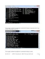
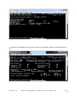
Page 36: ...stall Guide Rev G 36 To verify and or test your ASTRO 25 IP Modem II connectivity the following tests can be run from either the local or remote unit IP Ping From the ASTRO 25 IP Modem II Main menu select 12 Diagnostics From the Diagnostics menu select 13 IP Ping ...

Page 37: ...Modem II unit the unit currently logged onto and performing the diagnostic test Enter the number of packets to be transmitted The remainder of the parameters can be left as default After the last parameter is entered the ping test will commence A successful ping test will show ICMP packets returned from the remote ASTRO 25 IP Modem II An unsuccessful ping test will not show ICMP packets returned i...

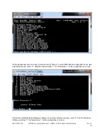
Page 38: ...nostic test 14 in the Diagnostics menu can assist in identifying where the routing or continuity is broken Enter the IP Addresses for the remote and local ASTRO 25 IP Modem II units and leave the remaining parameters defaulted The last IP address reported in the trace result is where the connection is failing Examine Port Network Services Router ...

Page 39: ...m II models in the Examine menu 2 of the Main menu The Port and Network Services have been configured by the MEM files previously uploaded to the units They will differ slightly between the ASTRO 25 Analog Modem II and the ASTRO 25 IP Modem II models Both models utilize Port 1 and Port 7 To verify these settings from the Examine menu enter 2 for Port Enter 1 for Port 1 ...

Page 40: ...5 IP Modem II Install Guide Rev G 40 Port 1 settings for ASTRO 25 Analog Modem II and ASTRO 25 IP Modem II models Note the Port Type is TBOP and the Interface Type is V 24 Port 7 settings for ASTRO 25 Analog Modem II and ASTRO 25 IP Modem II models ...

Page 41: ...25 Analog Modem II ASTRO 25 IP Modem II Install Guide Rev G 41 Port 10 settings for an ASTRO 25 Analog Modem II model Note the Port Type is FRI Clock Speed is 28800 and the Control Protocol Support is Annex_D Verify Router ...

Page 42: ...ASTRO 25 IP Modem II model can be verified by examining the IP Interface States IP Address Static Route Table and or the Default Subnet Gateway From the Examine Menu enter 16 Examine Router From the Examine Router menu enter 1 Examine Interface States Enter 1 for Router Interface 1 The Interface State should be Enabled ...

Page 43: ...e Rev G 43 Hit the Escape Key to back out to the Examine Router menu Enter 4 Examine IP Enter 2 for Interfaces and then 1 for Interface 1 Ensure the IP Address and IP Address Mask are configured correctly for the unit location Local Remote provided by your IP Administrator ...

Page 44: ...mine IP Menu To verify Static Route configuration if one was entered previously Enter 5 Static Routes and then 1 for Table Entry 1 Verify configuration is correct To Examine Default Subnet Gateway settings if one was entered previously enter 6 from the Examine IP Menu and then 1 for Table Entry 1 Verify configuration is correct ...

Page 45: ...I Install Guide Rev G 45 Port Status Statistics To check the operational status of configured connected ASTRO 25 Analog Modem II ASTRO 25 IP Gateway models Enter 5 Status statistics from the Main Menu From the Status statistics menu enter 2 Detailed Port Stat ...

Page 46: ...eck the Status of Port 1 Verify the Port Type is TBOP Port Status is Up and Port Speed is 9600 By continually re examining Port 1 you should observe Characters In Out and Frames In Out increment Hit the Escape key and Enter 7 to check the Status of the Voice Port It should be in the Running state ...

Page 47: ...0049 3200 100 ASTRO 25 Analog Modem II ASTRO 25 IP Modem II Install Guide Rev G 47 On ASTRO 25 Analog Modem II models Port 10 Status should also be verified The Port Status should Up ...

Page 48: ...r is longer This warranty extends to the original end user only b What This Warranty Does Not Cover This warranty does not cover a software b installation or service of the product c conditions resulting from consumer damage such as improper maintenance or misuse abuse accident or alteration d all plastic surfaces including display screens and all other exposed parts that are scratched or damaged ...

Page 49: ...ts SOME STATES DO NOT ALLOW THE EXCLUSION OR LIMITATION OF INCIDENTAL OR CONSEQUENTIAL DAMAGES OR LIMITATIONS ON HOW LONG AN IMPLIED WARRANTY LASTS THE ABOVE LIMITATIONS OR EXCLUSIONS MAY NOT APPLY TO YOU This warranty gives you specific legal rights and you may also have other rights which vary from State to State e Provincial Law Rights SOME PROVINCIAL LAWS DO NOT ALLOW THE EXCLUSION OR LIMITATI...

Page 50: ...r Telenetics product an RMA number must be obtained The most convenient way to obtain an RMA number for a product purchased from Raymar Telenetics is to call 1 800 747 1522 When doing so please have the following information ready Company name Full billing address as well as the address for the location where the product should be returned once repaired or replaced Telephone Fax numbers Email addr...

Page 51: ...yed on the shipping carton Raymar Telenetics will not be responsible for any product returned without an RMA number If the product is out of warranty estimates for repair rates and any applicable shipping costs will be communicated by a customer service representative Currently Raymar Telenetics accepts purchase orders or credit cards as payment methods Repairs currently require 5 10 business days...

Reviews: