0049-1200-XXX RM16M – USER’S GUIDE 12/29/2010
Rev. C
Page 18
of
27
APPENDIX B – DIGITAL INTERFACE DESCRIPTIONS
This appendix lists the digital interface descriptions. The information in this appendix may vary,
depending on modem type. Consult the manual for the particular PC card you are using.
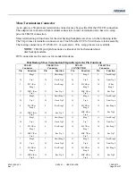
Table B-1. Digital Interface Signal Descriptions (232-C)
Pin No.
EIA-232C
CCITT
Signal Name
Description
1 AA 101
Protective
Ground
or Earth Ground
Chassis ground. Isolated from signal
ground or common return (pin 7).
2
BA
103
Transmit Data
Serial digital data (to be modulated) from
a data terminal or other digital data
source.
3
BB
104
Received Data
Serial digital data at the output of the
modem receiver. Data is accompanied by
an internal data rate clock (pin 17) whose
positive-going transitions occur on the
data transition. (Synchronous modems
only).
4
CA
105
Request to Send
A positive level to the modem when data
transmission is desired.
5
CB
106
Clear to Send
A positive level from the modem after
receipt of Request to Send (pin 4) and
when the modem is ready to transmit.
6
CC
107
Data Set Ready
A positive level from the modem when
power is on and it is ready to operate.
7
AB
102
Signal Ground or
Common Return
Common signal and DC power ground.
Isolated from protective ground (pin 1).
8 CF 109
Received
Line
Signal Detector
A positive level from the modem
indicating the presence of a receive signal
(carrier detect).
9
+12 volts
+12 voltage reference
10
-12 volts
-12 voltage reference
11
Not
used
12
SCF
Sec. Received Line
Signal Detector
Carrier detect on a secondary channel.
13
SCB
142
Sec. Clear to Send
Clear to send on a secondary channel.


