Chapter 4: Disassembly and Reassembly
Type 150/150G/400/400G Course Computers Service Manual 83156-1
19
Type 150/400 Course Computers
Step 2 - System Checks
•
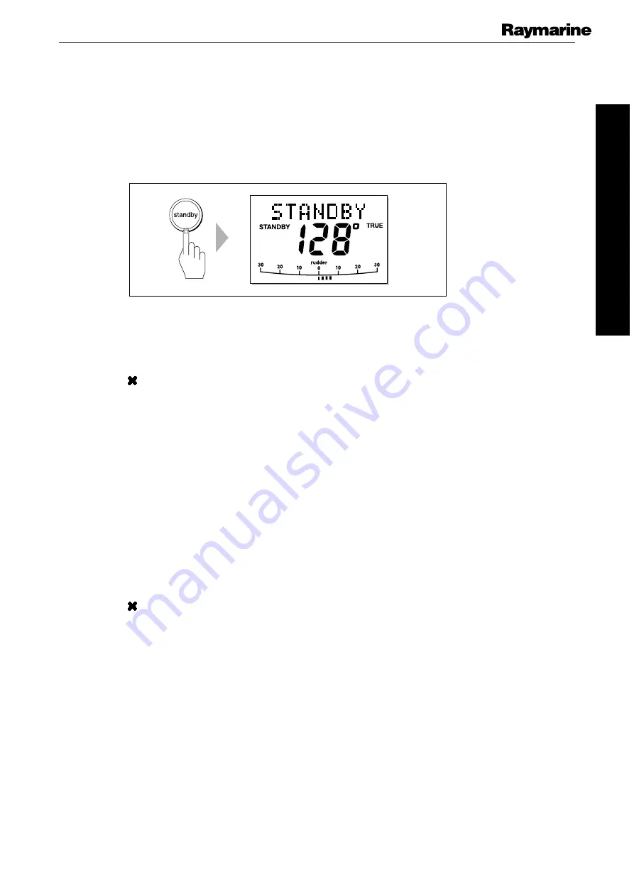
Check that the display shows a compass heading (the actual heading displayed is
unimportant at this stage) and that a rudder angle bar is displayed.
Note:
With a rudder reference fitted, the rudder bar will read full scale in one
direction due to the internal spring mechanism.
D3561-3
If both of these are present, this confirms that the Seatalk communications are
functioning correctly. Proceed to
Step 3
If these are not correct, return the Course Computer to your nearest Raymarine
Service Center.
Step 3 – Rate Gyro (if fitted)
If you are testing a T150G or T400G, it is necessary to test whether the internal rate gyro is
functioning correctly.
•
Using a Digital Voltmeter set to measure DC, measure the voltage at the rate gyro
terminals on the front connector strip. If the rate gyro is serviceable, the reading
should be between 2.1V and 2.9V.
If the voltage is within these limits, proceed
If the compass display does not match the change in orientation of the compass,
return the Course Computer to your nearest Raymarine Service Center.
•
With the multimeter still connected, turn the Course Computer slowly, first
clockwise, then anticlockwise.
If the rate gyro unit is functioning correctly, the voltage should increase (from
2.5V) as the Course Computer is turned in one direction and decrease (from 2.5V)
as it is turned in the opposite direction.
If the voltage changes as described, disconnect the rate gyro from the PCB (see
diagram) and proceed to
Step 4


