background image

a Series
c Series
e Series 

Installation instructions

English

Date: 05-2015
Document number: 87247-1-EN
© 2015 Raymarine UK Limited

a Series / c Series / e Series installation instructions

Summary of Contents for A series

Page 1: ...a Series c Series e Series Installation instructions English Date 05 2015 Document number 87247 1 EN 2015 Raymarine UK Limited...

Page 2: ......

Page 3: ...patents design patents patents pending or design patents pending Fair Use Statement You may print no more than three copies of this manual for your own use You may not make any further copies or dist...

Page 4: ......

Page 5: ...Power NMEA Video cable 43 4 10 a6x and a7x to NMEA 0183 DSC VHF radio connection 44 4 11 Sonar module and transducer connection 45 4 12 Radar network connection 46 4 13 GA150 connection 49 4 14 GNSS...

Page 6: ...Touchscreen alignment 122 9 14 Miscellaneous troubleshooting 123 Chapter 10 Technical specification 125 10 1 a Series 126 10 2 c and e Series 130 Chapter 11 Technical support 135 11 1 Raymarine custom...

Page 7: ...quipment with the power switched on unless instructed in this document Warning FCC Warning Part 15 21 Changes or modifications to this equipment not expressly approved in writing by Raymarine Incorpor...

Page 8: ...ng Disclaimers This product including the electronic charts is intended to be used only as an aid to navigation It is designed to facilitate use of official government charts not replace them Only off...

Page 9: ...l doit accepter toute interf rence notamment les interf rences qui peuvent affecter son fonctionnement Cet appareil num rique de la classe B est conforme la norme NMB 003 du Canada Japanese approvals...

Page 10: ...LAS The equipment described within this document is intended for use on leisure marine boats and workboats NOT covered by International Maritime Organization IMO and Safety of Life at Sea SOLAS Carria...

Page 11: ...and product information Chapter contents 2 1 Document information on page 12 2 2 Product documentation on page 12 2 3 Document illustrations on page 13 2 4 Product overview on page 13 Document and pro...

Page 12: ...e Accepted methods of payment for printed manuals are credit cards and PayPal Printed manuals can be shipped worldwide Further manuals will be added to the Print Shop over the coming months for both n...

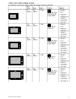
Page 13: ...play variants a6x multifunction displays are available in the following variants Non sonar variant a65 E70162 Sonar variant a67 E70163 DownVision variant a68 E70201 display only E70207 with CPT 100 tr...

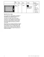
Page 14: ...LONASS receiver GA150 external antenna connection Controls Multi Touch touchscreen HybridTouch when paired with a remote keypad a12x Display variants a12x multifunction displays MFDs are available in...

Page 15: ...Bluetooth Wi Fi NMEA 0183 NMEA 2000 via SeaTalkng Internal GPS Video input e95 E70021 e97 E70022 e Series HybridTouch Touchscreen and physical buttons Bluetooth Wi Fi NMEA 0183 NMEA 2000 via SeaTalkn...

Page 16: ...physical buttons which can be used in addition to the touchscreen Touchscreen only multifunction displays which do not have physical buttons can be connected to a remote keypad which allows HybridTouc...

Page 17: ...ariant on page 25 3 5 Networking constraints on page 25 3 6 System protocols on page 26 3 7 Data master on page 27 3 8 a6x and a7x parts supplied on page 28 3 9 a9x and a12x parts supplied on page 28...

Page 18: ...D Raymarine RCU 3 Bluetooth 2 Mobile device Smartphone Tablet 1 per multifunction display For Raymarine wireless video streaming and remote control apps Apple iPhone 4 or later or iPad 2 or later Andr...

Page 19: ...ed or Tridata i60 Wind CH Wind i70 ST70 ST70 SeaTalk via optional SeaTalk to SeaTalkng converter i40 Wind Speed Depth or Bidata ST60 Wind Speed Depth Rudder or Compass ST40 Wind Speed Depth Rudder or...

Page 20: ...rboard alert 1 basestation All Raymarine Lifetag basestations SeaTalk via optional SeaTalk to SeaTalkng converter 12 Engine interface Raymarine 1 unit for each engine CAN bus ECI 100 SeaTalkng 12 Engi...

Page 21: ...rnal sonar variant displays 15 DownVision transducers 1 Direct connection to internal CHIRP DownVisionTM variant displays CPT 100 Transom mount CPT 110 Thru hull plastic CPT 120 Thru hull bronze Direc...

Page 22: ...tions to multifunction display NMEA inputs 2 NMEA 0183 compatible chartplotters and multifunction displays NMEA 0183 19 Sonar Modules Fishfinder Raymarine Multiple CP100 DownVision CP200 SideVision CP...

Page 23: ...Multiple Fusion 700 series entertainment systems MS IP700 MS AV700 SeaTalkhs 24 PC laptop 1 Windows compatible PC or laptop running Raymarine Voyage Planner software SeaTalkhs Note Raymarine cannot gu...

Page 24: ...his exercise is NOT completed the system will automatically attempt to resolve data conflicts However this may result in the system choosing a source of data that you do not want to use If MDS is avai...

Page 25: ...d as the Data Master The Data Master display will receive data through NMEA 0183 and or SeaTalkng and bridge the data over SeaTalkhs to other networked displays Homescreen sharing When networked MFDs...

Page 26: ...does not use all of the connection types or instrumentation described in this section SeaTalkhs SeaTalkhs is an ethernet based marine network This high speed protocol allows compatible equipment to c...

Page 27: ...are used some examples of which are VTG carries Course and Speed Over Ground data GLL carries latitude and longitude DBT carries water depth MWV carries relative wind angle and wind speed data NMEA B...

Page 28: ...9 a9x and a12x parts supplied The following items are supplied with your a9x and a12x variant MFD D13066 1 x4 1 4 7 9 10 11 5 6 8 2 3 1 Front bezel 2 Multifunction display MFD 3 Mounting gasket 4 Sun...

Page 29: ...ludes Multilingual CD Mounting and getting started multilingual guide Mounting template Warranty policy 8 Power and data cable 9 Trunnion bracket kit 3 11 c Series and e Series parts supplied The part...

Page 30: ...nent are provided later in this chapter Mounting surface Ensure product is adequately supported on a secure surface Do not mount units or cut holes in places which may damage the structure of the vess...

Page 31: ...ove decks D11537 2 1 2 3 1 2 3 1 This location provides optimal GPS performance above decks 2 In this location GPS performance may be less effective 3 This location is NOT recommended for GPS antenna...

Page 32: ...stallation to enable you to best judge which location gives the optimum viewing angle Viewing angle 000 000 000 000 000 00000 00000 00000 D12576 1 C D A B a6x a7x a9x a12x A Right 60 75 80 80 B Left 6...

Page 33: ...26 mm 16 8 in B 144 mm 5 67 in 173 1 mm 6 81 in 222 mm 8 74 in 281 4 mm 11 1 in C 30 mm 1 18 in 31 4 mm 1 24 in 31 9 mm 1 26 in 31 4 mm 1 24 in D 63 5 mm 2 5 in 63 9 mm 2 5 in 68 9 mm 2 71 in 69 8 mm...

Page 34: ...34 a Series c Series e Series installation instructions...

Page 35: ...d transducer connection on page 45 4 12 Radar network connection on page 46 4 13 GA150 connection on page 49 4 14 GNSS GPS connection on page 49 4 15 AIS connection on page 50 4 16 Fastheading connect...

Page 36: ...hot objects Secure cables in place using tie wraps or lacing twine Coil any extra cable and tie it out of the way Where a cable passes through an exposed bulkhead or deckhead use a suitable watertigh...

Page 37: ...5 c97 c127 a65 a75 a67 a68 a7 7 a78 0 0 0 0 0 0 0 0 0 0 Power Data Trans ducer DownVi sion trans ducer SeaTalkng SeaTalkhs RayNet Network 1 SeaTalkhs RayNet Network 2 Video in out Power Video NMEA 018...

Page 38: ...ve a 3 pin power cable Refer to the Connections Overview section to establish the power connection for your MFD 6 2 4 5 3 D13282 2 1 1 MFD 2 3 pin power cable 3 Connection to power supply 4 Red cable...

Page 39: ...the Power connection section for more information on how to identify the wires in your product s power cable and where to connect them See below for more information on implementation for some common...

Page 40: ...rical installations as detailed in the following standards BMEA Code of Practice for Electrical and Electronic Installations in Boats NMEA 0400 Installation Standard ABYC E 11 AC DC Electrical Systems...

Page 41: ...les Typical SeaTalkng system 0 0 D12176 5 12 V 24 Vdc 1 2 6 9 10 8 7 3 4 5 1 SeaTalkng instrument 2 SeaTalkng pilot control head 3 iTC 5 converter 4 Wind transducer 5 MFD 6 Power supply 7 SeaTalkng au...

Page 42: ...connect each NMEA 2000 device on a spur OR connect the display on a spur into an existing NMEA 2000 backbone Important You cannot have 2 backbones connected together Connecting NMEA 2000 equipment to...

Page 43: ...output 4800 or 38400 baud rate Port 2 Input only 4800 or 38400 baud rate The baud rate for each input port must be specified in the System Settings menu Homescreen Set up System Settings NMEA Set up N...

Page 44: ...NMEA 0183 converter must be used to convert the SeaTalkng messages to NMEA 0183 messages The MFD and converter must be connected to the same SeaTalkng backbone 12 V dc 4 3 5 2 8 11 D12833 1 10 1 SeaT...

Page 45: ...e g CHIRP DownVisionTM sonar module Transducer connection Internal 600 W MFD direct connection 2 D12256 2 1 3 1 600 W sonar variant MFD 2 600 W MFD transducer Refer to 12 3 Digital ClearPulse Transduc...

Page 46: ...o systems which include Any number of MFD s with an internal sonar module plus a CP300 and or CP450C sonar module or No MFD s with an internal sonar module but more than one CP300 or CP450C sonar modu...

Page 47: ...d data digital cable extension is required D12254 1 1 4 2 3 1 Radar extension cable 2 Radar power and data digital cable 3 Raymarine network switch or crossover coupler if connecting Radar directly to...

Page 48: ...ote The maximum length for the radar power and data digital cable including any extensions is 25 m 82 ft RayNet Radar power and data digital cables These cables contain the wires for a scanner s power...

Page 49: ...th will result in signal degradation Connecting an external antenna Follow the steps below to connect the GA150 external antenna 1 3 2 4 D13074 1 1 Fully insert the antenna s cable connector into the...

Page 50: ...ctions provided with the unit 4 16 Fastheading connection If you wish to use MARPA radar target acquisition functions on your multifunction display you need either An autopilot connected to the multif...

Page 51: ...he alternate power connection For further information regarding keypad installation including power connection and mounting refer to the installation instructions supplied with the keypad Once connect...

Page 52: ...o the player s audio output 4 20 Video in out connection A camera video device or external display can be connected to MFDs that have a dedicated video in out connection Refer to the Connections overv...

Page 53: ...e12 1 x video in and 1 x video out VGA 4 21 IP Camera connection Raymarine IP cameras can be connected directly to the display s network connection or can be connected to the SeaTalkhs network via a...

Page 54: ...sted using a PC and the software supplied with the camera prior to adding the camera to the SeaTalkhs network Important Raymarine does not guarantee compatibility with third party IP cameras 4 22 Ther...

Page 55: ...hould connect 1 cable to each display For further information regarding thermal camera installation including power connection and mounting refer to the installation instructions supplied with the cam...

Page 56: ...0 connection Compatible Fusion NMEA 2000 marine entertainment systems can be connected to the SeaTalkng backbone The Fusion entertainment system can be controlled by any compatible MFD connected to th...

Page 57: ...t accompany the media player device 4 26 Raymarine mobile app connection You can use compatible tablet and smartphone devices as a wireless repeat display or remote control for your multifunction disp...

Page 58: ...and DOWN arrow buttons to highlight different on screen options The SHORTCUT button is used to select execute them During the pairing process you must define which of the arrow buttons you want to be...

Page 59: ...ft to right top to bottom order Press UP or DOWN arrow for momentary response Hold UP or DOWN arrow for continuous response Toggle menu items and options in dialogs and prompts in left to right top to...

Page 60: ...the connection between the 2 units press and hold any button on the RCU 3 for at least 3 seconds D13328 1 3 Seconds 10 15 20 25 30 Seconds 35 40 45 50 55 60 5 Note You will also need to reconnect the...

Page 61: ...Chapter 5 Mounting Chapter contents 5 1 Mounting a Series on page 62 5 2 Mounting c Series and e Series on page 64 Mounting 61...

Page 62: ...Slide the unit into place and secure using the provided fixings Note The supplied gasket provides a seal between the unit and a suitably flat and stiff mounting surface or binnacle The gasket should b...

Page 63: ...card door edge to ensure that the bezel sits flat 6 Check that the Power button and chart card door are free to operate Removing the front bezel Before proceeding ensure the memory card slot door is...

Page 64: ...pplied with the product to the selected location using masking or self adhesive tape 3 Using a suitable hole saw the size is indicated on the template make a hole in each corner of the cut out area 4...

Page 65: ...cables will take Attach the front bezel D12273 2 1 Mark the location of the mounting bracket screw holes on the chosen mounting surface 2 Drill holes for the fixings using a suitable drill ensuring t...

Page 66: ...ceeding ensure the memory card slot door is open D12275 1 2 1 2 1 Important Use care when removing the bezel Do not use any tools to lever the bezel doing so may cause damage 1 Place both your thumbs...

Page 67: ...iew HybridTouch and non Touch displays on page 73 6 10 Pages on page 75 6 11 Applications on page 77 6 12 Splitscreen controls on page 78 6 13 Screen overview on page 79 6 14 Initial set up procedures...

Page 68: ...t in PowerSave mode for prolonged periods of time When switching off the power to your vessel ensure that the unit is powered off using the power button For more information on the amount of power con...

Page 69: ...tions including all menu operations 2 Menu Accesses menus Press again to close menus 3 UniControl Provides a joystick rotary control and an OK push button for using menus and applications 4 Back Press...

Page 70: ...wer controls for external devices Press and hold to switch the unit OFF 9 Card reader slot Open the card door to insert or remove a MicroSD card There are 2 card slots labelled 1 and 2 used for electr...

Page 71: ...to indicate that the touchscreen is disabled All functions are still available using the physical buttons Touchscreen is locked All functions remain available using physical buttons Locking the touchs...

Page 72: ...open menus same effect as pressing the MENU button Using the cursor The cursor is used to move around the screen D7366_3 The cursor appears on the screen as a white cross D7368_2 If the cursor has not...

Page 73: ...mescreen overview HybridTouch and non Touch displays The Homescreen provides a central point of access for your display s applications data and settings The Homescreen provides quick access to your da...

Page 74: ...ting icon signifying that the scanner is on and transmitting When SCANNER is set to ON select this mode to activate the scanner This is the usual mode of operation Standby STBY Static icon indicating...

Page 75: ...n size of greater than 7 inches MFDs with a screen size of 7 inches or less can view pages with more than 2 application panes but only if they are sharing the Homescreen of an MFD which is capable of...

Page 76: ...either by selecting the relevant menu item or dragging it over to the displayed page 7 Select Finish The Rename Page dialog is displayed 8 Use the on screen keyboard to name the page then select Save...

Page 77: ...e from your radar scanner Data application view system and instrument data on your multifunction display for a range of compatible instruments Use the joystick or touchscreen to scroll through the ava...

Page 78: ...nge in or Range out controls to switch the active application between splitscreen and fullscreen views Selecting the active window e7 e7D When viewing a splitscreen page you can select the active appl...

Page 79: ...y connected equipment Applications to configure the settings for that particular application D12281 4 3 4 5 1 2 Screen item Description 1 Back On displays with a touchscreen you can press the onscreen...

Page 80: ...hrough the available menu items use the Rotary control Shortcuts page A number of useful functions can be accessed from the Shortcuts page D13004 1 1 3 5 7 8 4 2 6 1 Decrease display brightness 2 Incr...

Page 81: ...n to the menu Using slider bar controls Slider bar controls provide a graphical representation of numeric data and enables you to quickly change setting values 1 2 3 D12570 1 Item Descrip tion Non Tou...

Page 82: ...imum Vessel Draft i e the distance from the waterline to the lowest point of a vessel s keel Safety Margin an adequate clearance below the keel to allow for draft variation and changes in water or bot...

Page 83: ...Vessel displacement weight A vessel s height from the waterline will decrease when it is fully laden when compared with its unladen displacement Water type A vessel s height will decrease by approxima...

Page 84: ...GPS Set up For each satellite the screen provides the following information 1 2 3 D13122 1 1 Sky view 2 Satellite status 3 Position and fix information Sky view Sky view is a visual representation th...

Page 85: ...th compatible receivers to determine their location longitude latitude and altitude Operational GNSS GPS NAVSTAR Global Positioning System US owned constellation of satellites that became fully operat...

Page 86: ...d Off Choosing differential satellites You can select which constellations of SBAS your receiver will use From the GPS Set up menu Homescreen Set up System Settings GPS Set up 1 Select Differential Sy...

Page 87: ...l will switch the control between On and Off On a system containing multiple displays the pilot control is enabled on all displays at the same time Enabling the autopilot control function Evolution au...

Page 88: ...nd Using the engine identification wizard information Make the data connections according to the instructions provided in the 87202 ECI Installation instructions Ensure all data buses are powered up i...

Page 89: ...ternal Devices Engines Set up 2 If required change the number of engines your vessel has by selecting Num of Engines and entering the correct number of engines You can select up to 5 engines 3 Select...

Page 90: ...e to the following devices MFDs networked using SeaTalkhs MFDs networked using SeaTalkng SeaTalkng instruments displays networked using SeaTalkng SeaTalk instruments displays networked via a SeaTalk t...

Page 91: ...ff to turn simulator mode off Note The Demo movie option is for retail demonstration purposes only 6 21 Pairing the keypad The keypad can control 1 or more multifunction displays Multiple keypads can...

Page 92: ...ou can insert compatible chart cards into the unit s memory card reader Use branded chart cards and memory cards When archiving data or creating an electronic chart card Raymarine recommends the use o...

Page 93: ...ard or chart card From the homescreen 1 Select My Data 2 Select Eject Card A message is displayed prompting you to select the memory device you want to eject 3 Select SD1 for a memory card in the top...

Page 94: ...ant to eject 3 Select SD1 for a memory card in the top card slot or SD2 for a memory card in the bottom card slot 4 Open the chart card door located on the front right of the display 5 Push the edge o...

Page 95: ...available software against the software version of your Raymarine products 3 If the software on the website is newer than the software on your products download the relevant software package 4 Insert...

Page 96: ...your products Video tutorials Raymarine official channel on YouTube http www youtube com u ser RaymarineInc Video Gallery http www rayma rine co uk view id 2679 Product Support videos http www rayma...

Page 97: ...Chapter 7 System checks Chapter contents 7 1 GPS Check on page 98 7 2 Radar check on page 98 7 3 Sonar check on page 99 7 4 Thermal camera setup and checks on page 101 System checks 97...

Page 98: ...the radar scanner ensure all personnel are clear Warning Radar transmission safety The radar scanner transmits electromagnetic energy Ensure all personnel are clear of the scanner when the radar is t...

Page 99: ...nal sonar module All variants allow you to connect a compatible external sonar module or use an internal sonar module from a networked display The sonar channel you want to use must be selected from t...

Page 100: ...et Depths are measured from the transducer to the sea bed but you can apply an offset value to the depth data so that the displayed depth reading represents the depth to the sea bed from either the ke...

Page 101: ...u can pan and tilt the thermal camera image using the touchscreen Move your finger up and down the screen to tilt the camera up or down Move your finger left and right on the screen to rotate the came...

Page 102: ...102 a Series c Series e Series installation instructions...

Page 103: ...Chapter 8 Maintaining your display Chapter contents 8 1 Service and maintenance on page 104 8 2 Product cleaning on page 104 Maintaining your display 103...

Page 104: ...rofibre cloth is ideal 3 If necessary use a mild detergent to remove grease marks Note Do NOT use solvents or detergents on the screen itself Note In certain conditions condensation may appear inside...

Page 105: ...n page 110 9 6 Sonar crosstalk interference on page 113 9 7 Thermal camera troubleshooting on page 115 9 8 System data troubleshooting on page 117 9 9 Video troubleshooting on page 118 9 10 Wi Fi trou...

Page 106: ...ng subjected to comprehensive test and quality assurance programs However if you experience problems with the operation of your product this section will help you to diagnose and correct problems in o...

Page 107: ...close to the unit as possible to establish actual voltage when the current is flowing Refer to the Technical Specification section of your product s installation instructions for power supply requirem...

Page 108: ...Check the status of the Raymarine network switch SeaTalkhs RayNet network problem Check that SeaTalkhs RayNet cables are free from damage Software mismatch between equipment may prevent communication...

Page 109: ...n GPS connection fault Ensure that external GPS connections and cabling are correct and fault free External GPS antenna in poor position For example Below decks Close proximity to transmitting equipme...

Page 110: ...are secure clean and free from corrosion replace if necessary Software mismatch between equipment may prevent communication Ensure all Raymarine products contain the latest available software check t...

Page 111: ...are secure clean and free from corrosion replace if necessary 6 With the product under load using a multi meter check for high voltage drop across all connectors fuses etc this can cause the Fishfind...

Page 112: ...eed element Install transducer with speed element to enable speed readings Incorrect transducer selected no speed displayed Select a transducer that supports speed measurement from the Transducer Set...

Page 113: ...o be active at a time disable any other sonar modules by changing the Fishfinder application pane to a single one which only displays the output from one sonar module Alternatively disable the ping fo...

Page 114: ...ence from your system However this will not impede your ability to benefit from the full capabilities of your sonar system Being able to easily identify the way in which interference is displayed in t...

Page 115: ...or via a Raymarine network switch Check the status of the Raymarine network switch Network problem Check that SeaTalkhs RayNet cables are free from damage Control conflict e g caused by multiple users...

Page 116: ...ay benefit from a different Scene Mode setting For example a very cold background such as the sky could cause the camera to use a wider temperature range than appropriate Use the SCENE button Image fr...

Page 117: ...trument or engine interface Check the power to the SeaTalk bus Data source e g ST70 instrument or engine interface is not operating Refer to the manufacturer s handbook for the equipment in question I...

Page 118: ...uses and solutions are described here Problem Possible causes Possible solutions No signal message on screen video image not displayed Cable or connection fault Check that the connections are sound an...

Page 119: ...with Raymarine app Recommended device requirements iOS Devices Best performance achieved on iPhone 4 or later and iPad 2 or later Android Kindle Fire Best performance achieved with 1GHz processor and...

Page 120: ...nnection Media player device is not compatible with the Bluetooth 2 1 EDR power class 1 5 supported profile AVRCP 1 0 or higher Check the Bluetooth compatibility with the device manufacturer If the de...

Page 121: ...Screen is not being operated with bare fingers for example gloves are being worn Bare fingers must make contact with the screen for correct operation Alternatively you may use conductive gloves Touchs...

Page 122: ...up 2 Select Maintenance 3 Select Touchscreen Alignment 4 Place your finger over the on screen object momentarily then remove it 5 Repeat the action a further 3 times 6 If the operation was successful...

Page 123: ...lay Check that the power source is of the correct voltage and sufficient current Software mismatch on system upgrade required Go to www raymarine com and click on support for the latest software downl...

Page 124: ...124 a Series c Series e Series installation instructions...

Page 125: ...Chapter 10 Technical specification Chapter contents 10 1 a Series on page 126 10 2 c and e Series on page 130 Technical specification 125...

Page 126: ...ng bracket 238 3 mm 9 4 in Height including bracket 248 14 mm 9 8 in Depth NOT including cables 84 1 mm 3 3 in Depth including cables 164 5 mm 6 5 in Weight bare unit 3 68 kg 8 1 lbs a6x Power specifi...

Page 127: ...tion 1 Note Power consumption figures represent a loaded system for sonar variants this includes an active 600 W transducer and DownVision variants includes an active CPT 100 transducer a12x Power spe...

Page 128: ...khs port 10 100 Mbits s GA150 1 x TNC type external GPS GLONASS antenna connection Video input 1 x BNC type video input connection Wireless connections Wi Fi 802 11 b g Bluetooth Bluetooth 2 1 EDR pow...

Page 129: ...TSC Connector type BNC female Output resolution 720p Internal storage Multifunction displays MFDs include internal storage that can be used to store recorded video and photos taken using the Camera ap...

Page 130: ...racket 145 mm 5 71 in Height including bracket 180 mm 7 09 in Depth NOT including cables 64 mm 2 52 in Depth including cables 160 mm 6 29 in Weight bare unit e7 1 465 kg 3 23 lb e7D 1 550 kg 3 42 lb W...

Page 131: ...ithin power cable 15 A Standard 20 mm glass fuse Power consumption Full brightness e7 10 W e7D 13 8 W PowerSave mode e7 4 3 W e7D 10 3 W Note Power consumption figures represent a loaded system and fo...

Page 132: ...nvironmental specification Environmental specifications below apply to all display variants Operating temperature 25 C to 55 C 13 F to 131 F Storage temperature 30 C to 70 C 22 F to 158 F Relative hum...

Page 133: ...iding System SBAS WAAS EGNOS MSAS Special features Active Jamming Reduction Operating frequency 1575 42MHz Signal Acquisition Automatic Almanac Update Automatic Geodetic Datum WGS 84 alternatives avai...

Page 134: ...se map Jeppesen world base map Compatible LightHouse cartography Vector LightHouse charts Raster LightHouse charts Compatible Navionics cartography Navionics Ready to Navigate Navionics Silver Navioni...

Page 135: ...Chapter 11 Technical support Chapter contents 11 1 Raymarine customer support on page 136 11 2 Learning resources on page 136 11 3 Third party support on page 137 Technical support 135...

Page 136: ...2 Select Maintenance 3 Select Diagnostics 4 Select Select Device 5 Select the relevant product from the list 6 Select Show All Data 11 2 Learning resources Raymarine has produced a range of learning r...

Page 137: ...arty support Contact and support details for third party suppliers can be found on the appropriate websites Fusion www fusionelectronics com Navionics www navionics com Sirius www sirius com Technical...

Page 138: ...138 a Series c Series e Series installation instructions...

Page 139: ...140 12 3 Digital ClearPulse Transducers and accessories on page 141 12 4 DownVisionTM transducers and accessories on page 142 12 5 Network hardware on page 143 12 6 RayNet to RayNet cables and connect...

Page 140: ...D e9x c9x e12x c12x e165 Trunnion bracket mount kit A62358 R70001 R70002 A80176 Front bezel Gun metal R62377 R70004 R70006 R70126 Rear bezel Gun metal N A R70027 R70028 N A Front bezel Black R70361 R7...

Page 141: ...es The transducers listed below can be connected directly to sonar variant MFDs Depth transducers Part number Image Mounting Housing A80170 In Hull P79 Depth and Temperature transducers Part number Im...

Page 142: ...any 600 watt sonar module compatible sonar transducer directly to a sonar variant multifunction display E66074 3 m 9 84 ft transducer extension cable 12 4 DownVisionTM transducers and accessories The...

Page 143: ...e connection of RJ45 SeaTalkhs devices to a HS5 RayNet network switch in conjunction with suitable adapter cables Enables 2 RJ45 SeaTalkhs cables to be connected together to extend the length of the c...

Page 144: ...ely attach to the twist lock on RayNet cables enabling you to pull the cables through conduits and other obstacles 5 3 RayNet to RayNet right angle coupler adapter Suitable for connecting RayNet cable...

Page 145: ...rtight fit Directly connect a Raymarine radar scanner with an RJ45 SeaTalkhs male cable to a RayNet network switch e g HS5 or LightHouse MFD 1 3 Adapter cable with a RayNet male plug on one end and an...

Page 146: ...Raymarine network switch via SeaTalkhs cables RayNet connector used for connecting Raymarine network switches and SeaTalkhs devices to the multifunction display via RayNet cables Also required for co...

Page 147: ...Cable Notes Backbone cable various lengths The main cable carrying data Spurs from the backbone are used to connect SeaTalkng devices T piece connector Used to make junctions in the backbone to which...

Page 148: ...aTalk devices to a SeaTalkng system SeaTalkng Inline terminator A80001 Provides direct connection of a spur cable to the end of a backbone cable No T piece required SeaTalkng Blanking plug A06032 ACU...

Page 149: ...o in out connector Q Q J JO O 2 2 Q Q J JO O 3 3 Q Q J JO O 4 4 Q Q J JO O 5 5 Q Q J JO O 6 6 Q Q J JO O 9 9 Q Q J JO O Q Q J JO O 2 2 4 4 Q Q J JO O 2 2 3 3 Q Q J JO O 7 7 Q Q J JO O 8 8 Q Q J JO O 2...

Page 150: ...NMEA2000 Connector type STNG Current source to network No current sourced for external devices Current sink from network 160mA Interface drive only Pin Signal 1 12V 2 0V 3 Screen 4 CanH 5 CanL 6 SeaT...

Page 151: ...ta GLC Geographic position loran C sentence GLL Geographic position latitude longitude GSA GPS DOP and active satellites GSV GPS satellites in view HDG Heading deviation and variation sentence HDT Hea...

Page 152: ...data messages transmitted by the GPS receiver are repeated to any appropriate devices connected to the display s NMEA 2000 bus Bridging only occurs when the data is being transmitted by an NMEA 0183...

Page 153: ...de 127258 Magnetic Variation 127488 Engine parameters rapid update 127489 Engine parameters dynamic 127493 Transmission parameters dynamic 127496 Trip parameters Vessel 127497 Trip parameters Engine 1...

Page 154: ...related message 129802 AIS Safety related broadcast message 129808 DSC call information 129809 AIS class B CS static data report part A 129810 AIS class B CS static data report part B 130306 Wind dat...

Page 155: ...n Sensor Engine Emergency Stop Mode Warning Level 1 Warning Level 2 Power Reduction Maintenance Needed Engine Comm Error Sub or Secondary Throttle Neutral Start Protect Engine Shutting Down unknown er...

Page 156: ...156 a Series c Series e Series installation instructions...

Page 157: ......

Page 158: ...www raymarine com...

Reviews: