Suppression ferrites
• Raymarine® cables may be pre-fitted or supplied with
suppression ferrites. These are important for correct
EMC performance. If ferrites are supplied separately
to the cables (i.e. not pre-fitted), you must fit the
supplied ferrites, using the supplied instructions.
• If a ferrite has to be removed for any purpose (e.g.
installation or maintenance), it must be replaced in the
original position before the product is used.
• Use only ferrites of the correct type, supplied by
Raymarine® or its authorized dealers.
• Where an installation requires multiple ferrites to be
added to a cable, additional cable clips should be
used to prevent stress on the connectors due to the
extra weight of the ferrites.
Connections to other equipment
Requirement for ferrites on non-Raymarine® cables.
If your AIS700 is to be connected to other equipment
using a cable not supplied by Raymarine®, a suppression
ferrite MUST always be attached to the end of the cable
near the AIS700.
RF interference
Certain third-party external electrical equipment can
cause Radio Frequency (RF) interference with GPS,
AIS or VHF devices if the external equipment is not
adequately insulated and emits excessive levels of
electromagnetic interference (EMI).
Some common examples of such external equipment
include LED spot or strip lights, and terrestrial TV tuners.
To minimize interference from such equipment:
• Keep it as far away from GPS, AIS or VHF devices as
possible.
• Ensure that any power cables for external equipment
are not entangled with the power or data cables for
GPS, AIS or VHF devices.
• Consider fitting one or more high frequency
suppression ferrites to the EMI-emitting device. The
ferrite(s) should be rated to be effective in the range
100 MHz to 2.5 GHz, and should be fitted to the power
cable and any other cables exiting the EMI-emitting
device, as close as possible to the position where the
cable exits the device.
Compass safe distance
To prevent potential interference with the vessel's
magnetic compasses, ensure an adequate distance is
maintained from the AIS700.
When choosing a suitable location for the AIS700 you
should aim to maintain the maximum possible distance
from any compasses. Typically this distance should be
at least 1 m (3 ft) in all directions. However for some
smaller vessels it may not be possible to locate the
AIS700 this far away from a compass. In this situation,
when choosing the installation location, ensure that the
compass is not affected by the AIS700 when it is in a
powered state.
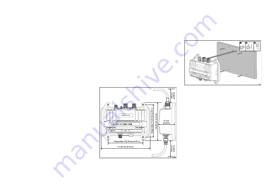
AIS700 dimensions
3.2 Mounting the AIS700
Before mounting the AIS700 ensure that you have:
• selected a suitable location (a clear, flat surface is
required).
• Identified the relevant cable connections and the
route that the cable will take.
1. Using the AIS700 as a guide, mark the location of the
mounting holes on the mounting surface.
2. Drill holes for the mounting fixings using a drill with
a suitable sized drill bit.
3. Screw the fixings approximately half way into the
holes in the mounting surface.
4. Place the AIS700 over the fixings screws and push
down to lock into position.
5. Fully tighten the screws.
6. Connect the necessary cables.
15


