1
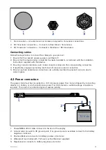
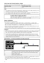
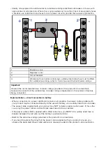
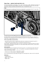
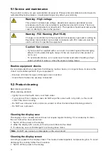
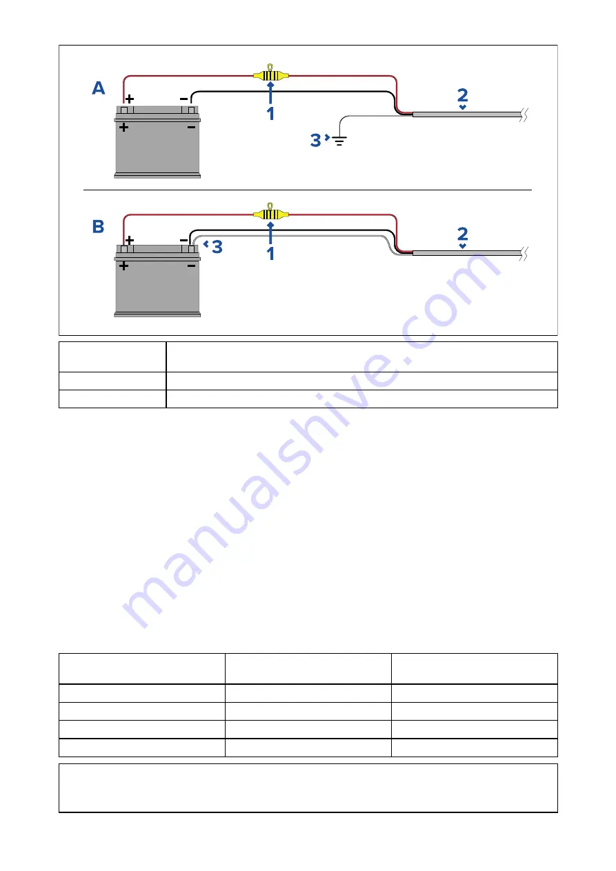
Waterproof fuse holder containing a suitably-rated inline fuse must be fitted.
For suitable fuse rating, refer to:
In-line fuse and thermal breaker ratings
.
2
Product power cable.
3
Drain wire connection point.
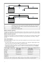
Battery connection scenario A:
Suitable for a vessel with a common RF ground point. In this scenario, if your product’s power cable is
supplied with a separate drain wire then it should be connected to the vessel’s common ground point.
Battery connection scenario B:
Suitable for a vessel without a common grounding point. In this case, if your product’s power cable is
supplied with a separate drain wire then it should be connected directly to the battery’s negative
terminal.
Power cable extension
If you need to extend the length of the power cable supplied with your product, ensure you observe
the following advice:
• The power cable for each unit in your system should be run as a separate, single length of 2-wire
cable from the unit to the vessel's battery or distribution panel.
• Ensure that the extension cable is of a sufficient gauge for the supply voltage and the total load
of the device and the length of the cable run. Refer to the following table for typical
minimum
power cable wire gauges.
Cable length in meters (feet)
Wire gauge in AWG (mm
2
) for
12 V supply
Wire gauge in AWG (mm
2
) for
24 V supply
<8 (<25)
16 (1.31 mm
2
)
18 (0.82 mm
2
)
16 (50)
14 (2.08 mm
2
)
18 (0.82 mm
2
)
24 (75)
12 (3.31 mm
2
)
16 (1.31 mm
2
)
>32 (>100)
10 (5.26 mm
2
)
16 (1.31 mm
2
)
Important:
Be aware that some products in your system (such as sonar modules) can create voltage peaks at
certain times, which may impact the voltage available to other products during the peaks.
42


