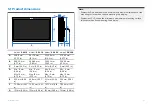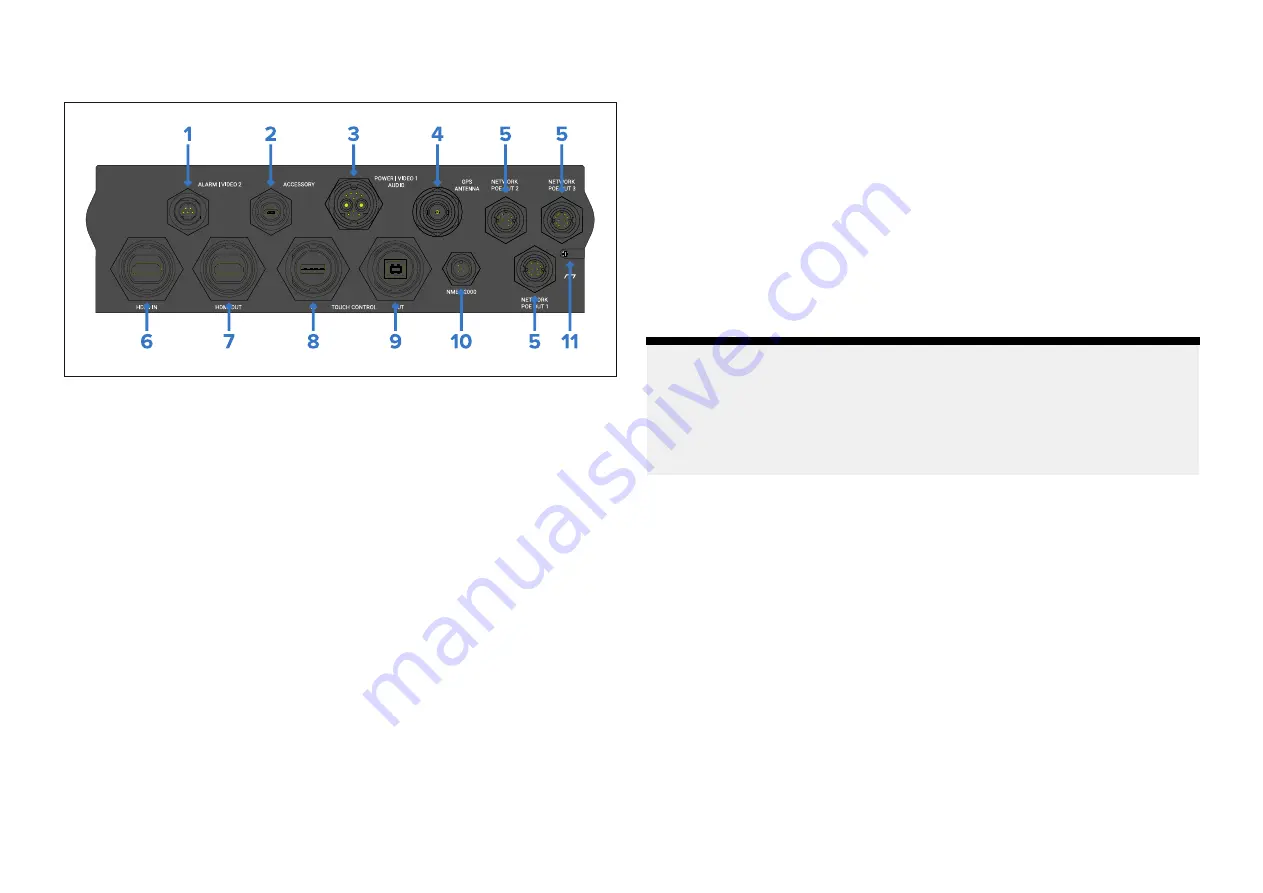
8.2 Connections overview
1.
ALARM | VIDEO 2
— The alarm / video 2 connector enables connections
of the external alarm buzzer accessory (E26033) and an analog video
input via BNC connector, using the alarm / video cable (part number
A80235).
2.
ACCESSORY
— The accessory connector enables connection of the
external card reader RCR-SD/USB (part number A80440).
3.
POWER | VIDEO 1 | AUDIO
— The power / video / audio connector
provides a connection to a 12 / 24 V dc power supply, an analog video
input via BNC connector, and analog audio output via RCA connectors.
4.
GPS ANTENNA
— The GPS antenna connector enables connection of an
external GNSS (GPS) antenna (e.g.: GA200 part number A80589), which
allows the display’s internal GNSS (GPS) receiver to obtain a position fix.
5.
NETWORK POE OUT
— The 3 x network connectors enable connection
of RayNet devices. The Network connectors also provide power to PoE
devices.
6.
HDMI IN
— The HDMI in connector enables connection of an external
HDMI video source using the HDMI cable (part number A80219). The
video source can be displayed in the display’s Video app.
7.
HDMI OUT
— The HDMI out connector enables connection of an external
HDMI monitor or HDTV using the HDMI accessory cable (part number
A80219). The monitor mirrors the display’s screen.
8.
TOUCH CONTROL IN
— The touch in connector enables you to control
the display with a compatible touchscreen monitor, using the USB A to
USB B cable (part number A80578).
9.
TOUCH CONTROL OUT
— The touch out connector enables you to
control a compatible device with the display’s touchscreen, using the
USB B to USB A cable (part number A80579).
10.
NMEA 2000
— The NMEA 2000 connector enables connection to a
SeaTalkng ® or NMEA 2000 network using the supplied SeaTalkng ® to
DeviceNet adaptor cable or a suitable DeviceNet cable.
11.
GROUND
— The optional grounding point should only be used when the
display experiences touchscreen interference from nearby equipment.
The grounding point should be connected to the same RF ground point
as the interfering equipment, or the vessel’s negative battery terminal.
Note:
• The
HDMI IN
and
VIDEO 2
connections share internal hardware and
cannot be used at the same time. If devices are connected to both
connections, the
HDMI IN
connection takes priority.
• The video feeds connected to the
HDMI IN
and
VIDEO 2
connections
are NOT streamed on the RayNet network.
8.3 Connecting cables
Follow the steps below to connect the cable(s) to your product.
1. Ensure that the vessel's power supply is switched off.
2. Ensure that the device being connected has been installed in accordance
with the installation instructions supplied with that device.
3. Ensuring correct orientation, push cable connectors fully onto the
corresponding connectors.
4. Engage any locking mechanism to ensure a secure connection (e.g.: turn
locking collars clockwise until tight, or in the locked position).
5. Ensure any bare ended wire connections are suitably insulated to prevent
shorting and corrosion due to water ingress.
Cables and connections — General information
37
Summary of Contents for AXIOM 2 XL
Page 2: ......
Page 4: ......
Page 22: ...CHAPTER 5 PRODUCT DIMENSIONS CHAPTER CONTENTS 5 1 Product dimensions page 23 22...
Page 39: ...CHAPTER 9 POWER CONNECTIONS CHAPTER CONTENTS 9 1 Power connection page 40 Power connections 39...
Page 56: ...CHAPTER 13 AUDIO CONNECTIONS CHAPTER CONTENTS 13 1 Audio RCA connections page 57 56...
Page 95: ...RayNet to RJ45 and RJ45 SeaTalkhs adapter cables Spares and accessories 95...
Page 102: ......
Page 107: ......

