background image

CHAPTER 9: POWER CONNECTIONS

CHAPTER CONTENTS

9.1 Power connection — page 40

Power connections

39

Summary of Contents for AXIOM 2 XL

Page 1: ...Document number 2023 Raymarine UK Limited 87445 Rev 3 02 2023 Date English en US INSTALLATION INSTRUCTIONS MFD CHARTPLOTTER AXIOMTM 2 XL...

Page 2: ......

Page 3: ...FLIR Systems Inc All other trademarks trade names or company names referenced herein are used for identification only and are the property of their respective owners This product is protected by pate...

Page 4: ......

Page 5: ...Document illustrations 13 2 5 Product documentation 13 User manuals Print Shop 14 2 6 LightHouse 4 operation instructions 14 Multifunction display software version 14 CHAPTER 3 PRODUCT AND SYSTEM OVER...

Page 6: ...Power distribution 40 Grounding optional grounding point 43 CHAPTER 10 NETWORK CONNECTIONS 44 10 1 NMEA 2000 SeaTalkng connection 45 10 2 NMEA 0183 connection 45 10 3 Network connection 46 Cable supp...

Page 7: ...on 77 18 3 LCD specification 77 18 4 Physical specification 77 18 5 Connections specification 78 18 6 Internal GNSS GPS receiver specification 78 18 7 Conformance approvals 79 18 8 Product markings 79...

Page 8: ...ver specification 90 21 7 Conformance approvals 91 21 8 Product markings 91 CHAPTER 22 SPARES AND ACCESSORIES 92 22 1 Accessories 93 22 2 Spares 93 22 3 RayNet to RayNet cables and connectors 94 RayNe...

Page 9: ...OT install in a hazardous flammable atmosphere such as in an engine room or near fuel tanks Product warnings Caution Product weight Refer to the technical specification for your product to ensure the...

Page 10: ...antenna 2 Increase the separation between the equipment and receiver 3 Connect the equipment into an outlet on a circuit different from that to which the receiver is connected 4 Consult the dealer or...

Page 11: ...nic equipment at a recycling center or other collection point For more information about suitable collection points for waste electrical and electronic equipment in your region refer to the Raymarine...

Page 12: ...APTER CONTENTS 2 1 Applicable products page 13 2 2 Document information page 13 2 3 Document conventions page 13 2 4 Document illustrations page 13 2 5 Product documentation page 13 2 6 LightHouse 4 o...

Page 13: ...g square brackets Examples You can select your desired cartography from the Cartography selection menu MFD apps are accessed from the Homescreen Procedures for performing specific tasks using the prod...

Page 14: ...e Print Shop FAQ pages http www raymarine co uk view id 5751 Note Accepted methods of payment for printed manuals are credit cards and PayPal Printed manuals can be shipped worldwide Further manuals w...

Page 15: ...CHAPTER 3 PRODUCT AND SYSTEM OVERVIEW CHAPTER CONTENTS 3 1 Product overview page 16 3 2 Additional components page 17 3 3 Typical systems page 17 Product and system overview 15...

Page 16: ...n power video audio cable connected to amplifier entertainment system 2x Analog video inputs BNC connectors one via supplied power video audio cable and a second via optional alarm video cable A80235...

Page 17: ...Capturing and viewing screenshots or images png jpg files Recording and viewing video files mov files Installation of third party LightHouse app apk files for installation only apps cannot be run dir...

Page 18: ...ar transducer RVM 100 illustrated 8 Raymarine radar scanner Cyclone illustrated Example expanded system 1 Raymarine thermal camera M300 illustrated 2 YachtSense Link Marine Router 3 EV 1 Evolution aut...

Page 19: ...work switch RNS 5 illustrated 14 Autopilot controller P70s illustrated 15 ACU Evolution autopilot drive not shown 16 YachtSense Digital Control System Master module assembly illustrated 17 External Ra...

Page 20: ...CHAPTER 4 PARTS SUPPLIED CHAPTER CONTENTS 4 1 Parts supplied page 21 4 2 Additional parts supplied in MFD kit page 21 20...

Page 21: ...hers M5 nuts and mounting feet 6 M3 x 5 screw M3 spring washer and M3 crimp terminal for optional grounding connection 7 Documentation 8 SeaTalkng to DeviceNet adaptor cable 1 m 3 3 ft 9 RayNet networ...

Page 22: ...CHAPTER 5 PRODUCT DIMENSIONS CHAPTER CONTENTS 5 1 Product dimensions page 23 22...

Page 23: ...4 in Max 19 mm 0 75 in Min 6 mm 0 24 in Max 19 mm 0 75 in Min 6 mm 0 24 in Max 19 mm 0 75 in E 253 mm 9 96 in 294 mm 11 57 in 331 mm 13 03 in 392 mm 15 43 in F 73 96 mm 2 91 in 73 95 mm 2 91 in 79 75...

Page 24: ...ts page 25 6 3 Axiom 2 XL 24 above decks installation requirements page 25 6 4 GNSS GPS location requirements page 26 6 5 Touchscreen location requirements page 26 6 6 Wireless location requirements f...

Page 25: ...prevent stress on connectors If your installation requires multiple ferrites to be added to a cable then additional cable clips should be used to ensure the extra weight of the cable is supported Wat...

Page 26: ...elements may exhibit the following Hot Touchscreen temperature If the display is mounted where it will be exposed to prolonged periods of direct sunlight the touchscreen may become hot Erroneous Touch...

Page 27: ...s range may experience slow connection speeds signal dropouts or not being able to connect at all For best results the wireless product should have a clear direct line of sight to the product it will...

Page 28: ...between different items of electrical equipment to provide the best conditions for EMC performance throughout the installation RF interference Certain third party external electrical equipment can ca...

Page 29: ...e 30 7 2 Mounting options page 30 7 3 Rear access requirements page 30 7 4 Preparing the mounting surface surface mounting page 31 7 5 Preparing the mounting surface flush mounting page 31 7 6 Fitting...

Page 30: ...justable wrench 9 4 mm Hex wrench Allen key Note Items are only required when flush mounting the display 7 2 Mounting options Axiom 2 XL displays can be mounted flush with the mounting surface flush m...

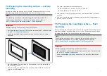
Page 31: ...t out line The corner diameter for the displays are 15 40 mm 0 61 in Axiom 2 XL 16 19 and 24 13 5 mm 0 53 in Axiom 2 XL 22 3 Use a jigsaw or similar cutting tool to cut out the remainder of the cut ou...

Page 32: ...h of 9 00 mm 0 35 in 6 Use a half round file and or sandpaper to smooth and rough edges or burs on the cut out hole 7 6 Fitting the gasket tape Before fitting the display you must fit the mounting gas...

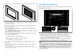
Page 33: ...ng bars to the back of the display using the supplied countersunk screws in the 4 locations shown 4 Secure the display using the provided mounting fixings M5 bolt wavy washer nut and foot in the 4 loc...

Page 34: ...Warning Marine grade sealant Only use marine grade neutral cure polyurethane sealants Do NOT use sealants containing acetate or silicone which can cause damage to plastic parts 34...

Page 35: ...TIONS GENERAL INFORMATION CHAPTER CONTENTS 8 1 General cabling guidance page 36 8 2 Connections overview page 37 8 3 Connecting cables page 37 8 4 Bare end wire connections page 38 Cables and connecti...

Page 36: ...e passes through an exposed bulkhead or deckhead use a suitable watertight feed through Do NOT run cables near to engines or fluorescent lights Always route data cables as far away as possible from Ot...

Page 37: ...er A80578 9 TOUCH CONTROL OUT The touch out connector enables you to control a compatible device with the display s touchscreen using the USB B to USB A cable part number A80579 10 NMEA 2000 The NMEA...

Page 38: ...d water ingress Bare ended wire connections It is recommended that bare ended wire connections are made by soldering or using crimp connectors and then protected by wrapping the connection in insulati...

Page 39: ...CHAPTER 9 POWER CONNECTIONS CHAPTER CONTENTS 9 1 Power connection page 40 Power connections 39...

Page 40: ...o your product Inline fuse rating Thermal breaker rating 15 A 15 A if only connecting one device Note The suitable fuse rating for the thermal breaker is dependent on the number of devices you are con...

Page 41: ...d power cable is connected to a suitable breaker or switch on the vessel s distribution panel or factory fitted power distribution point The distribution point should be fed from the vessel s primary...

Page 42: ...connection scenario A Suitable for a vessel with a common RF ground point In this scenario the power cable s drain wire should be connected to the vessel s common ground point Battery connection scena...

Page 43: ...y terminal The dc power system should be either Negative grounded with the negative battery terminal connected to the vessel s ground or Floating with neither battery terminal connected to the vessel...

Page 44: ...CHAPTER 10 NETWORK CONNECTIONS CHAPTER CONTENTS 10 1 NMEA 2000 SeaTalkng connection page 45 10 2 NMEA 0183 connection page 45 10 3 Network connection page 46 10 4 Power over Ethernet PoE page 47 44...

Page 45: ...2 NMEA 0183 connection The display can transmit and receive NMEA 0183 data when using a compatible NMEA 2000 to NMEA 0183 converter such as the Actisense NGW 1 converter part number A80721 connected...

Page 46: ...0183 device has only 3 NMEA 0183 wires the connection will differ from that described above Please see below for alternative wiring Connect to receiving device Converter signal wire color Receiving N...

Page 47: ...cing Equipment which supplies power over the network connections to connected PoE powered device PD The display can output a maximum of 32 Watts 26 W PD for consumption by up to 3 PoE powered devices...

Page 48: ...PoE devices should be connected using RayNet cables The ferrites supplied with your display must be used on all RayNet network connections In order to sufficiently power PoE devices the display s powe...

Page 49: ...VIDEO CONNECTIONS CHAPTER CONTENTS 11 1 Analog video Video 1 connection page 50 11 2 Analog video Video 2 connection page 50 11 3 HDMI IN connection page 50 11 4 HDMI OUT connection page 51 Video conn...

Page 50: ...is connected to the ALARM VIDEO 2 connector located on the rear of the display The video feed can be viewed using the Video app 1 Display s ALARM VIDEO 2 connector 2 Video in Alarm out cable part numb...

Page 51: ...put device this can be Speakers connected to the audio connection on the display s Power Video Audio cable A Bluetooth speaker paired with the display Speaker or sound system connected directly to you...

Page 52: ...rted cable length is 20 m 65 6 ft Ensure that the locking collar is used to secure the connection to the display 1 Display 2 Display s HDMI OUT connector 3 HDMI cable part number A80219 Not supplied 4...

Page 53: ...CHAPTER 12 USB CONNECTIONS CHAPTER CONTENTS 12 1 Touch control input connection page 54 12 2 Touch out connection page 54 12 3 Accessory connection page 55 USB connections 53...

Page 54: ...lay 1 Display 2 Display s TOUCH CONTROL IN connector 3 Display s HDMI OUT connector 4 HDMI cable part number A80219 Not supplied 5 USB A to USB B cable part number A80578 Not supplied 6 HD touchscreen...

Page 55: ...wing video files mov files installation of third party LightHouse app apk files for installation only apps cannot be run directly from storage device connection of a compatible UAV drone for use with...

Page 56: ...CHAPTER 13 AUDIO CONNECTIONS CHAPTER CONTENTS 13 1 Audio RCA connections page 57 56...

Page 57: ...input RCA usually red male connector 5 Left auxiliary input RCA usually white or black male connector 6 Right RCA output red female connector 7 Left RCA output black female connector Note Audio can al...

Page 58: ...CHAPTER 14 ALARM BUZZER AND GNSS ANTENNA CONNECTIONS CHAPTER CONTENTS 14 1 External alarm connection page 59 14 2 GNSS GPS antenna connection page 59 58...

Page 59: ...he connection is secure and watertight 1 External alarm buzzer part number E26033 Not supplied 2 Connection Wires must be connected Black to Black and Red to Purple 3 Video in Alarm out cable part num...

Page 60: ...CHAPTER 15 MAINTAINING YOUR DISPLAY CHAPTER CONTENTS 15 1 Service and maintenance page 61 15 2 Product cleaning page 61 60...

Page 61: ...hat all cables are securely connected 15 2 Product cleaning Best cleaning practices When cleaning products Switch off power supply Use a clean damp cloth to wipe clean Do NOT use abrasive acidic ammon...

Page 62: ...ge 63 16 2 LED Diagnostics page 63 16 3 Power up troubleshooting page 64 16 4 GNSS GPS troubleshooting page 65 16 5 Sonar troubleshooting page 66 16 6 Wi Fi troubleshooting page 68 16 7 Touchscreen tr...

Page 63: ...luminated using LEDs The LED color and flash sequence identifies the status of the display along with any error codes LED indication Status and required action White Powered up Ok Normal operation no...

Page 64: ...ions Power supply and connection See possible solutions from the table above entitled Product does not turn on or keeps turning off Software corruption 1 In the unlikely event that the product s softw...

Page 65: ...GA150 must be connected to enable a position fix to be obtained Internal GNSS GPS receiver disabled When using your product s internal GNSS GPS receiver ensure that it is enabled in the relevant sett...

Page 66: ...e solutions Damaged or fouled transducer Check the condition of the transducer ensuring it is not damaged and is free from debris fouling clean or replace as necessary Wrong transducer fitted Ensure t...

Page 67: ...t too low Unpause or increase sonar scrolling speed Possible causes Possible solutions Sensitivity settings may be inappropriate for present conditions Check and adjust sensitivity settings or perform...

Page 68: ...rescan available networks Some devices may automatically turn off Wi Fi when not in use to save power Power cycle reboot devices and rescan available networks Possible cause Possible solutions Device...

Page 69: ...device causing the interference then remove or reposition the offending device s Possible cause Possible solutions Motion sensors Interference caused by electrical and electronic devices and associat...

Page 70: ...cation running slowly or not at all Possible cause Possible solutions Raymarine app not installed Install mobile app from relevant app store Raymarine app version not compatible with display software...

Page 71: ...the power source is of the correct voltage and sufficient current Software mismatch on system upgrade required Go to www raymarine com and click on support for the latest software downloads Corrupt d...

Page 72: ...CHAPTER 17 TECHNICAL SUPPORT CHAPTER CONTENTS 17 1 Raymarine product support and servicing page 73 17 2 Learning resources page 74 72...

Page 73: ...the Raymarine website for Manuals and Documents http www raymarine com manuals Technical support forum https raymarine custhelp com app home Software updates http www raymarine com software Worldwide...

Page 74: ...ntrol your display over an Internet connection for the purposes of technical support and troubleshooting To get started you will first need to contact Raymarine Product Support If the representative c...

Page 75: ...nformation http www raymarine co uk view id 2372 Technical support forum You can use the Technical support forum to ask a technical question about a Raymarine product or to find out how other customer...

Page 76: ...cation page 77 18 2 Environmental specification page 77 18 3 LCD specification page 77 18 4 Physical specification page 77 18 5 Connections specification page 78 18 6 Internal GNSS GPS receiver specif...

Page 77: ...55 C 131 F Storage temperature range 30 C 22 F to 70 C 158 F Humidity up to 93 40 C 104 F Water ingress protection IPx6 and IPx7 Installation location Above decks Below decks 18 3 LCD specification Sp...

Page 78: ...Fi connection Multi band 2 4GHz and 5Ghz 802 11b g n Dual MIMO Multiple In Multiple Out 2 4 GHz 1x Antenna is used for Wi Fi only 1x Antenna is used for both Wi Fi and Bluetooth 2 4GHz only can simult...

Page 79: ...t Directive 2014 53 EU EN 60945 2002 Europe Australia New Zealand FCC Part 15C and Part 15E ISED ICES 003 NMEA 2000 certified 18 8 Product markings The product includes the following approval complian...

Page 80: ...cation page 81 19 2 Environmental specification page 81 19 3 LCD specification page 81 19 4 Physical specification page 81 19 5 Connections specification page 82 19 6 Internal GNSS GPS receiver specif...

Page 81: ...5 C 131 F Storage temperature range 30 C 22 F to 70 C 158 F Humidity up to 93 40 C 104 F Water ingress protection IPx6 and IPx7 Installation location Above decks Below decks 19 3 LCD specification Spe...

Page 82: ...Fi connection Multi band 2 4GHz and 5Ghz 802 11b g n Dual MIMO Multiple In Multiple Out 2 4 GHz 1x Antenna is used for Wi Fi only 1x Antenna is used for both Wi Fi and Bluetooth 2 4GHz only can simult...

Page 83: ...t Directive 2014 53 EU EN 60945 2002 Europe Australia New Zealand FCC Part 15C and Part 15E ISED ICES 003 NMEA 2000 certified 19 8 Product markings The product includes the following approval complian...

Page 84: ...cation page 85 20 2 Environmental specification page 85 20 3 LCD specification page 85 20 4 Physical specification page 85 20 5 Connections specification page 86 20 6 Internal GNSS GPS receiver specif...

Page 85: ...5 C 131 F Storage temperature range 30 C 22 F to 70 C 158 F Humidity up to 93 40 C 104 F Water ingress protection IPx6 and IPx7 Installation location Above decks Below decks 20 3 LCD specification Spe...

Page 86: ...Fi connection Multi band 2 4GHz and 5Ghz 802 11b g n Dual MIMO Multiple In Multiple Out 2 4 GHz 1x Antenna is used for Wi Fi only 1x Antenna is used for both Wi Fi and Bluetooth 2 4GHz only can simult...

Page 87: ...t Directive 2014 53 EU EN 60945 2002 Europe Australia New Zealand FCC Part 15C and Part 15E ISED ICES 003 NMEA 2000 certified 20 8 Product markings The product includes the following approval complian...

Page 88: ...cation page 89 21 2 Environmental specification page 89 21 3 LCD specification page 89 21 4 Physical specification page 89 21 5 Connections specification page 90 21 6 Internal GNSS GPS receiver specif...

Page 89: ...e temperature range 30 C 22 F to 70 C 158 F Humidity up to 93 40 C 104 F Water ingress protection IPx6 and IPx7 Installation location Above decks protected from direct sunlight Below decks 21 3 LCD sp...

Page 90: ...Fi connection Multi band 2 4GHz and 5Ghz 802 11b g n Dual MIMO Multiple In Multiple Out 2 4 GHz 1x Antenna is used for Wi Fi only 1x Antenna is used for both Wi Fi and Bluetooth 2 4GHz only can simult...

Page 91: ...t Directive 2014 53 EU EN 60945 2002 Europe Australia New Zealand FCC Part 15C and Part 15E ISED ICES 003 NMEA 2000 certified 21 8 Product markings The product includes the following approval complian...

Page 92: ...CHAPTER 22 SPARES AND ACCESSORIES CHAPTER CONTENTS 22 1 Accessories page 93 22 2 Spares page 93 22 3 RayNet to RayNet cables and connectors page 94 22 4 SeaTalkng cables and accessories page 97 92...

Page 93: ...verter A80721 GA200 passive GNSS GPS antenna A80589 GA150 passive GNSS GPS antenna A80288 HDMI cable 5 m 16 4 ft cable A80219 Straight power video audio cable 1 5 m 4 92 ft A80744 RCR 1 card reader A8...

Page 94: ...le socket on the other end Suitable for connecting at 90 right angle to a device for installations where space is limited 3 RayNet cable puller 5 pack 4 RayNet to RayNet right angle coupler adapter Su...

Page 95: ...RayNet to RJ45 and RJ45 SeaTalkhs adapter cables Spares and accessories 95...

Page 96: ...locking gland for a watertight fit 3 Adapter cable with a RayNet male plug on one end and an RJ45 SeaTalkhs waterproof male plug on the other end 4 Adapter cable with a RayNet male plug on one end an...

Page 97: ...ach T piece allows connection of one SeaTalkng device Multiple T pieces can be daisy chained together 4 2 x Backbone terminators part number A06031 Terminators must be fitted to both ends of the SeaTa...

Page 98: ...1 x Power cable 2 m 6 6 ft part number A06049 Used to provide 12 V dc power to the SeaTalkng backbone 2 1 x Spur cable 1 m 3 3 ft part number A06039 Used to connect a device to the SeaTalkng backbone...

Page 99: ...A06037 SeaTalkng power cables SeaTalkng power cables are used to provide the SeaTalkng backbone with a single 12 V dc power source The power connection must include a 5 amp inline fuse not supplied 1...

Page 100: ...s are available SeaTalkng to DeviceNet female adaptor cable 0 4 m 1 3 ft part number A06045 SeaTalkng to DeviceNet female adaptor cable 1 m 3 3 ft part number A06075 5 SeaTalkng to DeviceNet male adap...

Page 101: ...NMEA 2000 PGNs please refer to the relevant Operations manual for your display LightHouse version Operations manual LightHouse 3 81370 LightHouse 4 81406 To obtain the latest version of the manual vi...

Page 102: ......

Page 103: ...eaning 61 Screen 61 Compass safe distance 28 Connecting cables 37 Connections Accessory 37 55 Alarm 37 Alarm buzzer 59 Analog camera 50 Analog video 50 Audio 57 Bare wires 38 Battery 42 Card reader 55...

Page 104: ...9 H HDMI 16 HDMI IN 50 Resolution 50 HDMI IN connection 54 HDMI OUT Resolutions 51 HDMI out connection 54 I Installation 30 32 Best practice 42 Flush mount 33 Mounting options 30 Surface mount 30 33 I...

Page 105: ...0 Backbone cables 99 Connectors 99 Kits 97 Power cables 99 Spur cables 98 SeaTalkng cables 97 SeaTalkng connection 45 Service Center 73 Servicing 61 Software updates 27 Spares 93 Support forum 75 Supp...

Page 106: ...Video app HDMI IN 50 Video connection 50 W Warranty 11 73 WEEE Directive 11 What s in the box 21...

Page 107: ......

Page 108: ...rine House Cartwright Drive Fareham Hampshire PO15 5RJ United Kingdom Tel 44 0 1329 246 700 www raymarine co uk Raymarine US 110 Lowell Road Hudson NH 03051 United States of America Tel 1 603 324 7900...

Reviews: