background image

Mounting the transducer

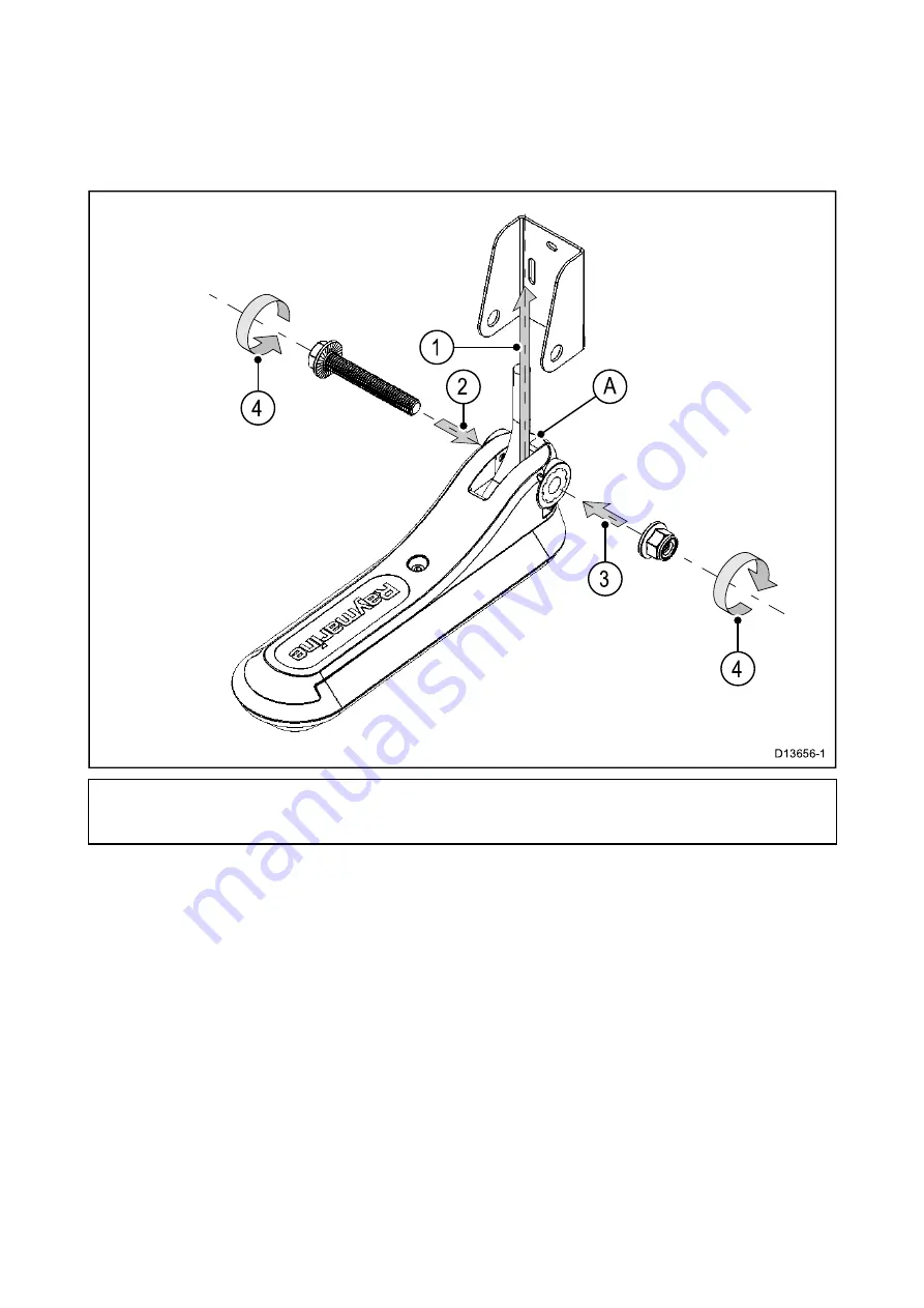
The transducer must be mounted on the transom using the mounting bracket provided. The steps
below describe the initial mounting steps required in order to test your transducer’s performance.
After testing the transducer you must finish the mounting following the instructions in the

Finishing

the transducer mounting

section.

Note: Before starting this procedure, check that the plastic chock (marked ‘A’ in the illustration)
is already positioned in front of the transducer cable. If it is not, push the chock into the correct
position, aligning the hole in the chock with the holes in the transducer hanger.

1. Position the transducer hanger between the mounting bracket arms, ensuring that the transducer

cable is routed between the arms, and the center hole is aligned with the holes in the arms.

2. Slide the flanged mounting bolt through the mounting bracket assembly.
3. Screw the flanged nyloc nut onto the end of the mounting bolt, and hand-tighten.
4. Using a pair of 14 mm wrenches, tighten the nut onto the mounting bolt until the transducer

hanger stays in position, but can still be adjusted by hand.

10

Summary of Contents for axiom 7

Page 1: ...2017 Raymarine UK Limited 87298 1 Document number 04 2017 Date English en US Installation instructions...

Page 2: ......

Page 3: ...ts design patents patents pending or design patents pending Fair Use Statement You may print no more than three copies of this manual for your own use You may not make any further copies or distribute...

Page 4: ......

Page 5: ...transducers for Fishfinder variant Axiom MFDs 16 RV 100 RealVision 3D Transom Mount Transducer 16 DownVision transducers 17 DownVision type CHIRP conical beam transducers 17 2 4 Parts supplied Axiom 7...

Page 6: ...connection 49 4 6 Accessory connection 50 Chapter 5 Maintaining your display 51 5 1 Service and maintenance 52 Routine equipment checks 52 5 2 Product cleaning 53 Cleaning the display case 53 Cleanin...

Page 7: ...nal GNSS GPS GLONASS receiver specification 76 Chapter 9 Spares and accessories 77 9 1 AXIOM accessories 78 9 2 AXIOM spares 79 9 3 RayNet to RayNet cables and connectors 80 RayNet to RJ45 adapter cab...

Page 8: ...8...

Page 9: ...lies with FCC IC RF exposure limits for general population uncontrolled exposure The wireless LAN Bluetooth antenna is mounted behind the front facia of the display This equipment should be installed...

Page 10: ...or mobile identification and amateur radio stations radio stations that require license used in industries such as microwave ovens scientific medical equipment devices and production line of other fac...

Page 11: ...will need this serial number when registering your product online You should retain the label for future reference Technical accuracy To the best of our knowledge the information in this document was...

Page 12: ...12...

Page 13: ...ble products on page 15 2 3 Compatible transducers for Fishfinder variant Axiom MFDs on page 16 2 4 Parts supplied Axiom 7 on page 18 2 5 Parts Supplied Axiom 7 DISP on page 19 2 6 Parts supplied Axio...

Page 14: ...product Visit http www raymarine co uk view id 5175 to order a printed manual delivered directly to your door For further information about the Print Shop please visit the Print Shop FAQ pages http w...

Page 15: ...7 MFD with built in RealVision 3D sonar module supplied with Rear mount kit only E70366 Axiom 9 9 MFD Chartplotter E70366 DISP Axiom 9 9 MFD Chartplotter supplied with Rear mount kit only E70367 Axiom...

Page 16: ...nsom Mount Transducer Part number Description Construction A80464 RV 100 RealVision 3D Transom Mount Transducer Plastic The RV 100 is a RealVision 3D transducer capable of producing 3D sonar images Th...

Page 17: ...ement for A80270 CPT 100 A80277 Thru hull CPT 110 plastic A80271 Thru hull CPT 120 bronze DownVision type CHIRP conical beam transducers Product number Transducer Mounting Description E70342 Transom C...

Page 18: ...for surface flush mounting 6 M5x58 Threaded studs x 4 7 M5 Thumb nuts x 4 8 Documentation pack 9 Power NMEA 2000 cable with 1 5 m 4 92 ft power lead and 0 5 m 1 64 ft NMEA 2000 lead E70364 01 is also...

Page 19: ...d E70365 DISP 1 MFD 2 Rear mount brackets x 2 3 Suncover Surface mount 4 Panel mount gasket for surface flush mounting 5 M5x58 Threaded studs x 4 6 M5 Thumb nuts x 4 7 Documentation pack 8 Right angle...

Page 20: ...ied with 9 MFD b supplied with 12 MFD 7 Documentation pack 8 Power NMEA 2000 cable with 1 5 m 4 92 ft power lead and 0 5 m 1 64 ft NMEA 2000 lead 9 M5x58 Threaded studs x 4 10 M5 Thumb nuts x 4 E70367...
Page 21: ...369 DISP 1 MFD 2 Panel mount gasket for surface flush mounting 3 Suncover 4 M5x58 Threaded studs x 4 5 M5 Thumb nuts x 4 6 Rear mounting brackets a supplied with 9 MFD b supplied with 12 MFD 7 Documen...

Page 22: ...22...

Page 23: ...3 1 Selecting a location on page 24 3 2 Mounting options on page 31 3 3 Bracket Trunnion mounting on page 32 3 4 Axiom 7 flush and surface mounting on page 33 3 5 Surface or flush mounting using the R...

Page 24: ...quipment Any specific requirements for each system component are provided later in this chapter Mounting surface Ensure product is adequately supported on a secure surface Do not mount units or cut ho...

Page 25: ...lude LED spot or strip lights and terrestrial TV tuners To minimize interference from such equipment Keep it as far away from GPS AIS or VHF devices as possible Ensure that any power cables for extern...

Page 26: ...can also have an impact In particular steel aluminium or carbon surfaces can impact GPS performance Before locating equipment with an internal GPS antenna below decks or on a steel aluminium or carbo...

Page 27: ...roducts Distance and signal strength The distance between Wi Fi products should always be kept to a minimum Do not exceed the maximum stated range of your Wi Fi product Maximum range will vary for eac...

Page 28: ...o best judge which location provides the optimum viewing angle Refer to Chapter 8 Technical specification for viewing angles for your product Product dimensions Axiom 7 trunnion mount dimensions A 250...

Page 29: ...n E Straight connectors 218 mm 8 58 in Right angled connectors 198 mm 7 79 in F 73 mm 2 87 in G 132 mm 5 2 in Axiom 9 and 12 trunnion mount dimensions Axiom 9 Axiom 12 A 265 03 mm 10 43 in 314 mm 12 3...

Page 30: ...Axiom 12 A 244 08 mm 9 64 in 314 mm 12 36 in B 157 78 mm 6 21 in 226 72 mm 8 93 in C 8 mm 0 31 in 8 mm 0 31 in D 100 8 mm 3 97 in 79 3 mm 3 12 in E 157 mm 6 18 in 222 mm 8 74 in F Straight connectors...

Page 31: ...t any installation requirements 1 Trunnion mount 2 Flush mount Mounting surface and MFD screen a level 3 Surface mount MFD screen protrudes slightly form mounting surface 4 Front mount using the Front...

Page 32: ...lied with the Axiom 9 and Axiom 12 are made from metal and so look different than the trunnion shown A metal trunnion bracket is also available for the Axiom 7 as an accessory Part number R70528 1 Usi...

Page 33: ...be removed before installation the unit using the Rear mount brackets or Front Installation kit 1 Unscrew the 4 x M5x16 screws using a 4 mm hex wrench Allen key 2 Pull the trunnion adaptor away from t...

Page 34: ...decks flush mount installations marine grade silicone should be used to seal the gap between the edge of the mounting surface and the edge of the MFD 5 Place the Trunnion adaptor over the back of the...

Page 35: ...D 3 Remove the backing from the gasket and attach it to the rear of the MFD ensuring that the black soft side is against the rear of the MFD 4 Insert the MFD into the cut out hole Important In above d...

Page 36: ...36...

Page 37: ...s 4 1 Connections overview on page 38 4 2 Power connection on page 41 4 3 NMEA 2000 SeaTalkng connection on page 46 4 4 Transducer connection on page 47 4 5 Network connection on page 49 4 6 Accessory...

Page 38: ...ector Connector Connects to Suitable cables Network connection RayNet network or device Refer to chapter Chapter 9 Spares and accessories for available cables Accessory connection RCR SDUSB memory car...

Page 39: ...ing additional dedicated drain wire required section for details Depending on MFD variant different transducer connections are available Transducer connection options Connector Connects to Suitable ca...

Page 40: ...ed has been installed in accordance with the installation instructions supplied with that device 3 Ensuring correct orientation push cable connectors fully onto the corresponding connectors 4 If appli...

Page 41: ...devices you are connecting If in doubt consult an authorized Raymarine dealer Your product s power cable may have an in line fuse fitted if not then you must add an in line fuse breaker to the positiv...

Page 42: ...d power cable is NOT fitted with an inline fuse you MUST fit a suitably rated fuse or breaker between the red wire and the battery s positive terminal Refer to the inline fuse ratings provided in the...

Page 43: ...e by 8 AWG 8 36 mm2 cable Ideally all equipment should be wired to individual suitably rated thermal breakers or fuses with appropriate circuit protection Where this is not possible and more than 1 it...

Page 44: ...e of 10 8 V at the product s power connector with a fully flat battery at 11 V Important Be aware that some products in your system such as sonar modules can create voltage peaks at certain times whic...

Page 45: ...s ground or Floating with neither battery terminal connected to the vessel s ground If several items require grounding they may first be connected to a single local point e g within a switch panel wi...

Page 46: ...000 network or SeaTalkng via adaptor cable 3 DeviceNet 5 pin female connector 4 Adaptor cable connects to SeaTalkng backbone or DeviceNet spur cable connects to NMEA 2000 network Available cables A060...

Page 47: ...ssary to extend the transducer cable 3 m 9 8 ft 5 m 16 4 ft and 8 m 26 2 ft transducer extension cables are available part numbers 3 m A80475 5 m A80476 8 m A80477 It is recommended that a maximum of...

Page 48: ...Embedded Transducers Y Cable A80492 Axiom RV to 25 pin RV 7 pin CP370 Transducers Y Cable A80493 Axiom RV to 7 pin Embedded 9 pin DV Transducers Y Cable A80494 Axiom RV to 7 pin CP370 9 pin DV Transd...

Page 49: ...one end of the RayNet cable to your MFD and the opposite end to a RayNet device or RayNet network switch 3 RayNet to RJ45 cable Connect the RayNet end of the cable to your MFD and the opposite end to...

Page 50: ...efer to the instructions provided with your accessory Warning Do NOT connect a USB device with an AC power source The following information only applies to Raymarine products which include a USB data...

Page 51: ...Chapter 5 Maintaining your display Chapter contents 5 1 Service and maintenance on page 52 5 2 Product cleaning on page 53 Maintaining your display 51...

Page 52: ...writing by Raymarine Incorporated could violate compliance with FCC rules and void the user s authority to operate the equipment Caution Sun covers If your product is supplied with a sun cover to prot...

Page 53: ...splay screen This will not harm the unit and can be cleared by powering on the display for a short time Cleaning the display screen A coating is applied to the display screen This makes it water repel...

Page 54: ...54...

Page 55: ...page 56 6 2 Power up troubleshooting on page 57 6 3 GNSS troubleshooting on page 58 6 4 Sonar troubleshooting on page 59 6 5 Wi Fi troubleshooting on page 62 6 6 Touchscreen troubleshooting on page 6...

Page 56: ...oducts are subjected to comprehensive testing and quality assurance programs If you do experience problems with your product this section will help you to diagnose and correct problems in order to res...

Page 57: ...ion instructions have been followed Power source insufficient With the product under load using a multi meter check the power supply voltage as close to the unit as possible to establish actual voltag...

Page 58: ...cation GNSS connection fault Ensure that external GNSS connections and cabling are correct and fault free External GNSS receiver in poor location For example Below decks Close proximity to transmittin...

Page 59: ...Wrong transducer fitted Ensure the transducer is compatible with your system External sonar module SeaTalkhs RayNet network problem Check that the unit is correctly connected to the multifunction dis...

Page 60: ...s as relevant and recheck Poor problematic image Possible causes Possible solutions Vessel stationary Fish arches are not displayed if the vessel is stationary fish will appear on the display as strai...

Page 61: ...uled transducer Check the condition of the transducer ensuring it is not damaged and is free from debris fouling Damaged transducer cable Check that the transducer cable and connection is free from da...

Page 62: ...ve power Power cycle reboot devices and retry the connection Trying to connect to the wrong Wi Fi network Ensure you are trying to connect to the correct Wi Fi network the Wi Fi network s name can be...

Page 63: ...i enabled or older Bluetooth enabled devices Bluetooth and Wi Fi both operate in the 2 4 GHz frequency range some older bluetooth devices may interfere with Wi Fi signals 1 Change the Wi Fi Channel of...

Page 64: ...t installed Install mobile app from relevant app store Raymarine app version not compatible with MFD software Ensure mobile app and MFD software are latest available versions Mobile apps not enabled o...

Page 65: ...ross the Power button swipe area to de activate the TouchLock Screen is not being operated with bare fingers for example gloves are being worn Bare fingers must make contact with the screen for correc...

Page 66: ...the display Check that the power source is of the correct voltage and sufficient current Software mismatch on system upgrade required Go to www raymarine com and click on support for the latest softwa...

Page 67: ...Chapter 7 Technical support Chapter contents 7 1 Raymarine product support and servicing on page 68 7 2 Learning resources on page 70 Technical support 67...

Page 68: ...ir flir com Web support Please visit the Support area of the Raymarine website for Manuals and Documents http www raymarine com manuals FAQ Knowledgebase http www raymarine com knowledgebase Technical...

Page 69: ...5 437 164 64 support dk raymarine com Raymarine subsidiary Russia 7 495 788 0508 info mikstmarine ru Authorized Raymarine distributor Viewing product information The Getting started tab contains hardw...

Page 70: ...nge of in depth training courses to help you make the most of your products Visit the Training section of the Raymarine website for more information http www raymarine co uk view id 2372 FAQs and Know...

Page 71: ...Chapter contents 8 1 Axiom tech spec on page 72 8 2 DownVision sonar specification on page 74 8 3 RealVision 3D sonar specification on page 75 8 4 Internal GNSS GPS GLONASS receiver specification on p...

Page 72: ...m 12 Size diagonal 7 0 9 0 12 1 Type TN Twisted Nematic IPS In Plane Switching Color depth 24 bit Resolution WVGA 800 x 480 WXGA 1280 x 800 Ratio 5 3 16 10 Illumination 1200 nits 1200 cd m2 Viewing an...

Page 73: ...1 b g n Bluetooth 1 x Bluetooth V4 0 Storage Axiom 7 Axiom 9 Axiom 12 Internal 4GB Solid State 2 GB usable External microSD card 1 x MicroSDXC card slot External via Accessory connection 1 x SD card s...

Page 74: ...y applies to DownVision products Channels 2 channels 1 x CHIRP sonar 1 x DownVision Beam coverage CHIRP sonar conical beam DownVision Wide port starboard and thin fore aft fan beam Range CHIRP sonar 0...

Page 75: ...ision 3D products Channels Channels 1 x CHIRP sonar 1 x DownVision 1 x SideVision 1 x RealVision 3D Range CHIRP sonar 0 6 M 2 ft to 274 m 900 ft DownVision 0 6 M 2 ft to 183 m 600 ft SideVision 0 6 M...

Page 76: ...S compatibility GPS GLONASS Beidou Galileo SBAS compatibility EGNOS GAGAN MSAS QZSS WAAS Operating frequency 1574 MHz to 1605 MHz Signal Acquisition Automatic Almanac Update Automatic Geodetic Datum W...

Page 77: ...accessories Chapter contents 9 1 AXIOM accessories on page 78 9 2 AXIOM spares on page 79 9 3 RayNet to RayNet cables and connectors on page 80 9 4 SeaTalk ng cables and accessories on page 83 Spares...

Page 78: ...2 x bezel pieces 4 x self tapping screws Front mount suncover A80499 7 Front mount suncover A80500 9 Front installation kit Includes Front mount adaptor 2 x bezel pieces 4 x self tapping screws Front...

Page 79: ...l trunnion mounting kit Includes trunnion and 2 knobs R70524 9 Plastic trunnion mounting kit Includes trunnion and 2 knobs R70529 9 Metal trunnion mounting kit Includes trunnion and 2 knobs R70530 9 T...

Page 80: ...bling you to pull the cables through conduits and other obstacles 5 3 RayNet to RayNet right angle coupler adapter Suitable for connecting RayNet cables at 90 right angle to devices for installations...

Page 81: ...at connects at the equipment end e g DSM300 will NOT be waterproof E55049 1 5m E55050 5m E55051 10m A62135 15m E55052 20m 1 2 Adapter cable with a RayNet female socket on one end and a waterproof fema...

Page 82: ...5 Adapter cable with a RayNet female socket on one end and an RJ45 SeaTalk hs female socket on the other end Connect a LightHouse MFD to a legacy SR6 switch weather receiver or a legacy 8 port SeaTalk...

Page 83: ...m 3 3ft backbone A06034 SeaTalk ng 3 m 9 8ft backbone A06035 SeaTalk ng 5 m 16 4ft backbone A06036 SeaTalk ng 9 m 29 5ft backbone A06068 SeaTalk ng 20 m 65 6ft backbone A06037 SeaTalk ng to bare ends...

Page 84: ...e Female A06045 Allows the connection of NMEA 2000 devices to a SeaTalk ng system DeviceNet adaptor cable Male A06046 Allows the connection of NMEA 2000 devices to a SeaTalk ng system DeviceNet adapto...

Page 85: ......

Page 86: ......

Page 87: ...allation Flush mounting 35 Flush mounting Axiom 7 only 33 Mounting options 31 Rear brackets 35 Surface mounting 35 Surface mounting Axiom 7 only 33 Trunnion mounting 32 Installation Best practice 44 I...

Page 88: ...W Warranty 68...

Page 89: ......

Page 90: ...Raymarine Marine House Cartwright Drive Fareham Hampshire PO15 5RJ United Kingdom Tel 44 0 1329 246 700 www raymarine com a brand by...

Page 91: ...REALVISION 2017 Raymarine UK Limited Document number 88067 1 Date 04 2017 English en US RV 100 3D Transom Transducer Installation instructions...

Page 92: ......

Page 93: ...s and refer to the separate warranty document packed with your product Warning High voltages This product may contain high voltages Do NOT remove any covers or otherwise attempt to access internal com...

Page 94: ...roduct online You should retain the label for future reference Product disposal Dispose of this product in accordance with the WEEE Directive The Waste Electrical and Electronic Equipment WEEE Directi...

Page 95: ...connected to RealVision 3D variant MFDs running LightHouse 3 software Note Additional mounting options are available for the RV 100 RealVision 3D transducer These include Part number A80479 RealVision...

Page 96: ...mounting surface you may require a different diameter drill bit Screws supplied are stainless steel tapping DIN 7049 ST with diameter 4 2 mm equivalent to a No 8 screw diameter 0 164 inch Three screws...

Page 97: ...ote The transducer is not suitable for mounting on vessels where the transom is aft of the propeller s For best performance the transducer must be installed in a location with the least turbulence and...

Page 98: ...and appear as aeration aft Note Optimum transducer location will vary depending on vessel type Optimum transducer height and angle should be obtained by testing the transducer with the vessel in the...

Page 99: ...or self adhesive tape 1 Transducer mounting template 2 Waterline 3 Mounting away from propeller 2 Ensure the template is parallel to the waterline 3 Drill 2 x holes for the adjustment slot screws as...

Page 100: ...ioned in front of the transducer cable If it is not push the chock into the correct position aligning the hole in the chock with the holes in the transducer hanger 1 Position the transducer hanger bet...

Page 101: ...l the hanger is held firmly in place The transducer position will be adjusted further during testing Note Do not adjust the M5 screw located on top of the transducer hanger This screw locates the tran...

Page 102: ...the locking collar Check that the cable is long enough to reach the equipment it will be connected to The following optional extension cables are available if required RealVision transducer extension...

Page 103: ...to accommodate the cable The plate is designed to fit over a 25 mm 1 inch diameter hole After you have threaded the transducer cable through the hole in the transom or bulkhead attach the escutcheon p...

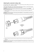
Page 104: ...you route the cable all the way to your multifunction display before attaching the locking collar 1 Slide the locking collar over the end of the connector then push it towards the cable end of the co...

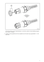
Page 105: ...des easily for approximately 1 cm onto the connector before butting up against the connector moulding 3 Carefully insert the pointed end of the supplied tool into the split ring s gap labelled C in th...

Page 106: ...to attach it without using the tool 4 Use the tool to gently lever the split ring over the moulding on the connector until it snaps into position approximately 0 5 cm further back towards the cable en...

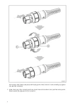
Page 107: ...ing collar towards the plug end of the connector rotating the collar as necessary to ensure that the lugs on the locking collar labelled D in the illustration pass through the channels labelled E in t...

Page 108: ...towards the plug end of the connector before butting up against the split ring moulding 7 Grasp the body of the connector with one hand then with the other hand pull the locking collar firmly towards...

Page 109: ...16 4 ft and 8 m 26 2 ft transducer extension cables are available part numbers 3 m A80475 5 m A80476 8 m A80477 It is recommended that a maximum of two cable extensions are used with the total cable...

Page 110: ...t point of the hull in the vicinity of the transducer 5 Loosen the mounting bolt to adjust the transducer angle 6 Loosen the 2 mounting bracket screws to adjust the transducer height 7 Re tighten the...

Page 111: ...g care not to damage the mounting bracket 2 Fill the locking hole with marine grade sealant 3 Secure the transducer and bracket by fully tightening all 3 mounting screws 4 Secure the transducer hanger...

Page 112: ...22...

Page 113: ......

Page 114: ...Raymarine Marine House Cartwright Drive Fareham Hampshire PO15 5RJ United Kingdom Tel 44 0 1329 246 700 www raymarine com a brand by...

Reviews: