background image

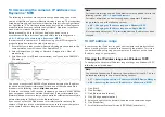
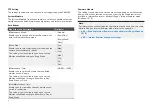
PTZ Setting

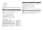
The settings found within this section are not supported by the CAM300.

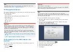
System Maintain

The

[System Maintain]

subsection contains a set of changeable automatic

maintenance schedules, firmware update options and factory reset options.

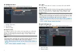
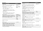
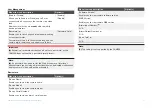
Auto Reboot

Menu item and description

Option(s)

[Maintenance Mode]

Enables you to change how often the camera will
enter a self-maintenance mode.

[Disable]

[Every Day]

[Every Week]

[Once]

[Week Plan]

Enables you to select which day(s) of the week the
camera will automatically reboot.

This setting is only available if you have set the
Maintenance Mode setting to Every Week.

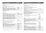
[Sun]

[Mon]

[Tue]

[Wed]

[Thu]

[Fri]

[Sat]

[Maintenance Time]

Enables you to select what time the scheduled
maintenance will begin.

This setting is only available if you have set the
Maintenance Mode setting to either Every Day,
Every Week, or Once.

[00:00]

[23:59]

[Next Maintenance Time]

Enables you to view when the next maintenance
period is scheduled.

This setting is only available if you have set the
Maintenance Mode setting to either Every Day or
Every Week.

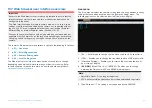
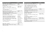
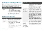
Firmware Update

The settings found within this section are not supported on a multifunction
display, and will not function unless you are using the Web browser user
interface in Internet Explorer or Microsoft Edge’s Internet Explorer mode
(Windows 10 / 11).

Note:

For information on the settings found within this section and how to enable
Microsoft Edge’s Internet Explorer mode, refer to the appendix:

p.85 — Enabling Internet Explorer mode on Microsoft Edge (Windows

10 / 11)

p.85 — Internet Explorer dependent settings

62

Summary of Contents for CAM300

Page 1: ...Document number 2023 Raymarine UK Limited 81411 Rev 1 01 2023 Date English en US INSTALLATION OPERATION INSTRUCTIONS HD DIGITAL MINIDOME IP CAMERA CAM300...

Page 2: ......

Page 3: ...FLIR Systems Inc All other trademarks trade names or company names referenced herein are used for identification only and are the property of their respective owners This product is protected by pate...

Page 4: ......

Page 5: ...re updates 14 3 3 Required additional components 14 3 4 System overview example only 15 Augmented Reality optional 16 CHAPTER 4 PARTS SUPPLIED 17 4 1 Parts supplied 18 4 2 Inline fuse requirement 18 I...

Page 6: ...Grounding not required 39 11 4 Power distribution 40 11 5 Power cable extension 12 V systems 41 CHAPTER 12 CAMERA SETUP AND OPERATION VIA RAYMARINE MFD 43 12 1 Setting up the camera via a Raymarine MF...

Page 7: ...R Troubleshooting 73 CHAPTER 17 TECHNICAL SUPPORT 74 17 1 Raymarine product support and servicing 75 Diagnostic product information 76 17 2 Learning resources 76 CHAPTER 18 TECHNICAL SPECIFICATION 77...

Page 8: ...cument Product warnings Warning 12 Volt dc only This product must ONLY be connected to a 12 V dc power source Warning Power supply voltage Connecting this product to a voltage supply greater than the...

Page 9: ...ng center or other collection point For more information about suitable collection points for waste electrical and electronic equipment in your region refer to the Raymarine website www raymarine eu r...

Page 10: ...CHAPTER 2 DOCUMENT INFORMATION CHAPTER CONTENTS 2 1 Applicable products page 11 2 2 Document illustrations page 11 2 3 Product documentation page 11 10...

Page 11: ...provided for illustration purposes only 2 3 Product documentation The following documentation is applicable to your product Applicable documents 81411 CAM300 Installation and Operation Instructions th...

Page 12: ...3 PRODUCT AND SYSTEM OVERVIEW CHAPTER CONTENTS 3 1 Product overview page 13 3 2 Compatible multifunction displays page 14 3 3 Required additional components page 14 3 4 System overview example only pa...

Page 13: ...ue day night operation Supports augmented reality features via the optional AR200 sensor and a compatible Raymarine multifunction display Waterproof to IPx6 12 V dc power Class 1 PoE device for easy s...

Page 14: ...rine com software for the latest software updates and the software update procedure for your specific product Important To prevent potential software related issues with your product always follow the...

Page 15: ...ble A62360 not supplied 4 RJ45 to RJ45 waterproof coupler 4115028 not supplied 5 RayNet female to RayNet female cable A80161 not supplied 6 PSE Power sourcing Equipment providing PoE Power over Ethern...

Page 16: ...ty on your system 1 PSE Power Sourcing Equipment providing PoE Power over ethernet to the camera Axiom XL currently illustrated 2 AR200 E70537 not supplied 3 SeaTalkng backbone 4 CAM300 connected to a...

Page 17: ...CHAPTER 4 PARTS SUPPLIED CHAPTER CONTENTS 4 1 Parts supplied page 18 4 2 Inline fuse requirement page 18 Parts supplied 17...

Page 18: ...ed to the red power wire housed in a waterproof fuse holder This fuse and its fuse holder are NOT supplied with your product and must be obtained separately from a marine or electrical retailer 1 Wate...

Page 19: ...CHAPTER 5 PRODUCT DIMENSIONS CHAPTER CONTENTS 5 1 Product dimensions page 20 Product dimensions 19...

Page 20: ...5 1 Product dimensions Item Dimension A 60 10 mm 2 37 in B 59 00 mm 2 32 in C 23 50 mm 0 93 in D 69 50 mm 2 74 in E 670 00 mm 2 2 ft approx 20...

Page 21: ...cautions page 22 6 2 General location requirements page 22 6 3 EMC installation guidelines page 22 6 4 Suppression ferrites page 23 6 5 Connections to other equipment page 23 6 6 Compass safe distanc...

Page 22: ...it in a protected area away from prolonged and direct exposure to rain and salt spray Electrical interference Select a location that is far enough away from devices that may cause interference such as...

Page 23: ...ways be attached to the cable near the Raymarine unit 6 6 Compass safe distance To prevent potential interference with the vessel s magnetic compasses ensure an adequate distance is maintained from th...

Page 24: ...e product must be calibrated with your MFD system in the Camera Installation page before Augmented Reality features can be used Please refer to your MFD operation instructions manual for more informat...

Page 25: ...CHAPTER 7 CABLES AND CONNECTIONS GENERAL INFORMATION CHAPTER CONTENTS 7 1 General cabling guidance page 26 7 2 Connections overview page 27 Cables and connections General information 25...

Page 26: ...te strain relief for cabling to ensure that connectors are protected from strain and will not pull out under extreme sea conditions Circuit isolation Appropriate circuit isolation is required for inst...

Page 27: ...ollowing 670 00 mm 2 20 ft approx connectors 1 RJ45 male ethernet 2 12 V dc power if powering the camera via PoE do NOT connect this to a 12 V dc feed Note For further network and power connection inf...

Page 28: ...NG CHAPTER CONTENTS 8 1 Tools required page 29 8 2 Camera orientation page 29 8 3 Mounting options page 30 8 4 Mounting the unit through surface cabling page 30 8 5 Mounting the unit above surface cab...

Page 29: ...camera can be mounted in 2 different orientations referred to as ball up upright and ball down upside down When mounting your camera ensure that the green infrared sensor is centered at the top as il...

Page 30: ...te to mark out the location of the mounting holes and the 24 mm 15 16 in cable feed hole 4 Drill the holes required at the marked locations 5 Remove the grub screws from the side of the camera s base...

Page 31: ...supplied hex wrench Allen key 6 Disconnect the camera body and collar from the base of the camera 7 Feed the fitted cable through the camera base s cable channel Example above surface cabling 8 Peel t...

Page 32: ...CHAPTER 9 NETWORK CONNECTIONS CHAPTER CONTENTS 9 1 Network cable connector types page 33 9 2 Network connection page 33 32...

Page 33: ...EVER connect a PoE device s dedicated power cable when it is being supplied PoE When the PoE device s dedicated power cable is not connected any bare end wire connections must be separately covered wi...

Page 34: ...etwork hardware and cables refer to the following section p 80 Spares and accessories Network cable extensions If you wish to extend the length of a network cable connected to your product you can ref...

Page 35: ...CHAPTER 10 POE POWER CONNECTIONS CHAPTER CONTENTS 10 1 Power options page 36 10 2 Power over Ethernet PoE page 36 PoE power connections 35...

Page 36: ...n the PoE device s dedicated power cable is not connected any bare end wire connections must be separately covered with insulation 10 2 Power over Ethernet PoE Power over Ethernet PoE is a system that...

Page 37: ...g required refer to the following section p 83 RayNet to RJ45 adapter cables Network cable extensions If you wish to extend the length of a network cable connected to your product you can refer to the...

Page 38: ...OWER CONNECTIONS CHAPTER CONTENTS 11 1 Power options page 39 11 2 Dedicated power connection page 39 11 3 Grounding not required page 39 11 4 Power distribution page 40 11 5 Power cable extension 12 V...

Page 39: ...dedicated power cable when it is being supplied PoE When the PoE device s dedicated power cable is not connected any bare end wire connections must be separately covered with insulation Warning 12 Vol...

Page 40: ...ers common vessel power arrangements but does NOT cover every scenario If you are unsure how to provide the correct level of protection please consult an authorized dealer or a suitably qualified prof...

Page 41: ...ower cable extensions advice provided in the product s documentation Item Description 1 Waterproof fuse holder containing a suitably rated inline fuse must be fitted For suitable fuse rating refer to...

Page 42: ...icient gauge ensure that there is a continuous minimum voltage of 10 8 V dc at the end of the cable where it enters the product s power connector even with a fully flat battery at 11 V dc Do not assum...

Page 43: ...APTER CONTENTS 12 1 Setting up the camera via a Raymarine MFD page 44 12 2 Camera operation via the Raymarine MFD Video app page 44 12 3 Camera operation via the Web interface LightHouse 4 LightHouse...

Page 44: ...evice list ensure that you have waited a sufficient amount of time before attempting to Refresh via the Network menu If correctly configured the CAM300 will appear on the Raymarine multifunction displ...

Page 45: ...via a Raymarine LightHouse 4 or LightHouse 3 multifunction display 1 From the Network menu Homescreen Settings Network 2 Select the CAM300 product description 3 Select the Calibrate option You will n...

Page 46: ...ons page 47 13 2 Accessing the camera s IP address via ONVIF Device Manager page 47 13 3 Accessing the camera s IP address via a Raymarine MFD page 48 13 4 IP address range page 48 13 5 Supported brow...

Page 47: ...l setup wizard s onscreen prompts 6 Double click and open the ONVIF Device Manager executable once the installation has finished The following ONVIF Device Manager homescreen will be displayed You can...

Page 48: ...ited a sufficient amount of time before attempting to Refresh via the Network menu If you cannot access the Web browser user interface after entering the camera s IP address into your default browser...

Page 49: ...e You will need to know the IP address of your product for step 8 This can be found by referring to one of the following sections p 47 Accessing the camera s IP address via ONVIF Device Manager p 48 A...

Page 50: ...Microsoft Edge Windows 10 11 p 85 Internet Explorer dependent settings 13 6 Logging in to the Web browser user interface You can login to the camera s Web browser user interface by using the followin...

Page 51: ...menu 4 p 63 Local Setting menu The Web browser user interface menu options are subject to change depending upon which firmware version your device is running Refer to the Raymarine website for details...

Page 52: ...icrosoft Edge Windows 10 11 p 85 Internet Explorer dependent settings Voice Alarm The settings found within this section are not supported by the CAM300 Overlay Settings The settings found within this...

Page 53: ...tional Overlay Information 1 Enables you to display both the camera resolution and bit rate on the onscreen display PC ONLY To move the location of the Additional Overlay Information setting that you...

Page 54: ...de setting to Automatic Passive Mode or Automatic Active Mode 3 15 Menu item and description Option s Day Time Enables you to set a specific start and end time when the camera s infrared filter will b...

Page 55: ...ent Warm Fluorescent Natural Manual Auto Locked Menu item and description Option s Red Gain Enables you to change the Red color gain of your camera s image By default this setting is set to 50 This se...

Page 56: ...preview This setting will only function if you have Enabled the Privacy Zone setting On Off Note 5 This setting is not supported on a multifunction display Web interface Network Config The Network Con...

Page 57: ...rt Config Menu item and description Options HTTP Port Enables you to configure your HTTP Hypertext Transfer Protocol Port setting HTTP Port Field Command Port Enables you to configure your Command Por...

Page 58: ...relevant LightHouse Operation instruction manuals Main Stream 3MP 2304 1296 1080P 1921 1080 720P 1280 720 Sub Stream 448P 800 448 D1 704 576 360P 640 360 CIF 352 288 Menu item and description Option s...

Page 59: ...tem Config The System Config submenu contains a set of changeable time and date settings user management settings PTZ Pan tilt zoom settings and a viewable device information page Time Setting Menu it...

Page 60: ...o Open pool ntp org time win dows com time nist gov time nw nist gov ntp1 inrim it time kriss re kr time nuri net time apple com Enable DST DST tab Allows you to enable or disable the DST Daylight Sav...

Page 61: ...rd reset process Note 9 If a password has been set for the Web browser user interface s administrator account image flip functionality via a dedicated multifunction display camera video app will be pr...

Page 62: ...me the scheduled maintenance will begin This setting is only available if you have set the Maintenance Mode setting to either Every Day Every Week or Once 00 00 23 59 Next Maintenance Time Enables you...

Page 63: ...respond The camera IP address will change after initiating a Full Recovery For instructions on how to find out the camera s IP address refer to the following section p 46 Camera setup via Windows 10 o...

Page 64: ...CHAPTER 14 AUGMENTED REALITY CHAPTER CONTENTS 14 1 Augmented Reality AR overview page 65 14 2 Augmented Reality optional page 65 64...

Page 65: ...ty feature requires correct camera calibration for accurate image overlay The Augmented Reality feature serves as an aid to navigation and situational awareness only and should not be solely relied on...

Page 66: ...ipment 5 12 V dc power supply providing power to the SeaTalkng backbone Note ClearCruise Augmented Reality is not available via the CAM300 s Web browser user interface For more information on ClearCru...

Page 67: ...CHAPTER 15 MAINTENANCE CHAPTER CONTENTS 15 1 Routine checks page 68 15 2 Unit cleaning instructions page 68 Maintenance 67...

Page 68: ...g mechanisms are properly engaged Note Cable checks should be carried out with the power supply switched off 15 2 Unit cleaning instructions The unit does not require regular cleaning However if you f...

Page 69: ...r connection troubleshooting page 70 16 3 PoE power connection troubleshooting page 70 16 4 Non PoE power connection troubleshooting page 71 16 5 IP camera troubleshooting page 71 16 6 Resetting the c...

Page 70: ...work so the camera is plugged into a non PoE ethernet connection Warning Powering PoE devices PoE devices can be powered via an ethernet connection PoE OR via a dedicated power cable NEVER connect a P...

Page 71: ...D is running the latest software version Troubleshooting issue User action s Try power cycling the camera while leaving your MFD powered Ensure that the IP Type and Auto IP settings found within the W...

Page 72: ...the Command Prompt application via the window s search bar at the bottom left hand side of your screen Once the Command Prompt application has opened type ping then the camera s local IP address in t...

Page 73: ...elevant options are enabled AR flags do not appear directly above on screen target Depending on the classification of the target s AIS hardware transmitted position updates may be sent up to 3 minutes...

Page 74: ...CHAPTER 17 TECHNICAL SUPPORT CHAPTER CONTENTS 17 1 Raymarine product support and servicing page 75 17 2 Learning resources page 76 74...

Page 75: ...site for Manuals and Documents http www raymarine com manuals Technical support forum https raymarine custhelp com app home Software updates http www raymarine com software Worldwide support United Ki...

Page 76: ...upport 2 Maintaining detailed off boat records This is particularly useful for vessels that have multiple Raymarine products installed To view or export diagnostic product information access the Diagn...

Page 77: ...ENTS 18 1 Physical specification page 78 18 2 Power specification page 78 18 3 Environmental specification page 78 18 4 Camera specification page 78 18 5 Video specification page 78 18 6 Conformance s...

Page 78: ...perature 30 C 22 F to 65 C 149 F Relative humidity up to 85 65 C 149 F Waterproof rating IPx6 18 4 Camera specification Specification ONVIF version 21 06 master version Sensor DSP 1 4 CMOS Sensor Scan...

Page 79: ...8 Section 8 Exposed EN IEC 60529 1989 A1 1999 A2 2013 for IPx6 IPx7 EMC Directive 2014 30 EU and UK EMC Regulations 2016 SI 2016 No 1091 EN 60945 2002 including Corrigendum 1 2008 RoHS Directive 2011...

Page 80: ...APTER 19 SPARES AND ACCESSORIES CHAPTER CONTENTS 19 1 Spares and accessories page 81 19 2 RayNet to RayNet cables and connectors page 82 19 3 RayNet to RJ45 and RJ45 SeaTalkhs adapter cables page 83 8...

Page 81: ...e following spare parts and accessories are available for your product E70537 AR200 SeaTalkng Augmented Reality Sensor 4113746 12 V Power over Ethernet PoE Injector 4115028 RJ45 to RJ45 waterproof cou...

Page 82: ...le socket on the other end Suitable for connecting at 90 right angle to a device for installations where space is limited 3 RayNet cable puller 5 pack 4 RayNet to RayNet right angle coupler adapter Su...

Page 83: ...19 3 RayNet to RJ45 and RJ45 SeaTalkhs adapter cables Spares and accessories 83...

Page 84: ...locking gland for a watertight fit 3 Adapter cable with a RayNet male plug on one end and an RJ45 SeaTalkhs waterproof male plug on the other end 4 Adapter cable with a RayNet male plug on one end an...

Page 85: ...n Menu item and description Option s Enable Human Shape Detection tab Allows you to Enable or Disable the Human Shape Detection setting which causes a green stick figure icon to be displayed on the br...

Page 86: ...pe To clear all Defense Areas drawn click the CLEAR button located underneath the video preview This setting will only function if you have enabled either the Human Shape Detection or Motion Detection...

Page 87: ...ware from a file located on your local drive Firmware update files can be downloaded from the Raymarine website www raymarine com software If in doubt as to the correct procedure for updating your pro...

Page 88: ......

Page 89: ...40 Non PoE connection 39 PoE connection 36 PoE Injector connection 37 Contact details 75 D Declaration of Conformity 9 Diagnostics 76 Exporting product information 76 Viewing product information 76 D...

Page 90: ...0 Fuses 18 Grounding 39 Sharing a breaker 40 Power cable extension 41 Product overview 13 Product recycling WEEE 9 Product support 75 R RayNet cables 82 83 Recording time 13 Required additional compon...

Page 91: ...ining courses 76 Troubleshooting 70 76 Augmented Reality 73 Camera reset 73 IP camera 71 Power connection 70 Non PoE 71 PoE 70 U Upgrading See Software updates V Ventilation 22 W Warranty 9 75 Web int...

Page 92: ......

Page 93: ......

Page 94: ...rine House Cartwright Drive Fareham Hampshire PO15 5RJ United Kingdom Tel 44 0 1329 246 700 www raymarine co uk Raymarine US 110 Lowell Road Hudson NH 03051 United States of America Tel 1 603 324 7900...

Reviews: