background image

14.3 GPS troubleshooting

Problems with the GPS and their possible causes and solutions are described here.

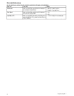
Problem

Possible causes

Possible solutions

Geographic location or prevailing
conditions preventing satellite fix.

Check periodically to see if a fix is obtained in better conditions or
another geographic location.

No GPS position.

Location of unit

For optimum performance the unit should be mounted above decks and
not be in close proximity to any structural bulkheads or other electrical
equipment or cables which may cause interference.

Note:

A GPS Status screen is available within the unit. This provides satellite signal strength and other relevant information.

94

Dragonfly / Dragonfly 7

Summary of Contents for Dragonfly

Page 1: ...Dra g o n flyTM Dra g o n flyTM 7 Installation and operation instructions English Date 03 2014 Document number 81345 3 EN 2014 Raymarine UK Limited Release 9...

Page 2: ......

Page 3: ...s patents pending or design patents pending Fair Use Statement You may print no more than three copies of this manual for your own use You may not make any further copies or distribute or use the manu...

Page 4: ......

Page 5: ...6 Getting started 35 6 1 Display power 36 6 2 Controls 36 6 3 Initial set up procedures 37 6 4 GPS Check 38 6 5 Sonar check 39 6 6 DownVision check 40 6 7 Shortcuts page 40 6 8 Applications 41 6 9 Vie...

Page 6: ...nar DownVision troubleshooting 95 14 5 Miscellaneous troubleshooting 96 Chapter 15 Technical support 97 15 1 Raymarine customer support 98 Chapter 16 Technical specification 99 16 1 Technical specific...

Page 7: ...NOT try to force a card into position DO NOT use a metallic instrument such as a screwdriver or pliers to insert or remove a chart or memory card Caution Ensure card reader door is securely closed To...

Page 8: ...portant to prevent erratic behavior and data loss which can occur if the engine start does not have a separate battery Raymarine specified cables are used Cables are not cut or extended unless doing s...

Page 9: ...vered by International Maritime Organization IMO and Safety of Life at Sea SOLAS Carriage Regulations Technical accuracy To the best of our knowledge the information in this document was correct at th...

Page 10: ...10 Dragonfly Dragonfly 7...

Page 11: ...Chapter 2 Document and product information Chapter contents 2 1 Document information on page 12 2 2 Product overview on page 13 Document and product information 11...

Page 12: ...ional instructions for the DragonflyTM and DragonflyTM 7 displays and CPT 60 transom mount transducer 81345 DragonflyTM surface mounting template DragonflyTM display surface mount adaptor cut out temp...

Page 13: ...s a water column directly beneath and to the sides of the vessel DownVisionTM beam D12777 2 DownVisionTM is effective at lower vessel speeds In deeper waters the CHIRP bandwidth is automatically optim...

Page 14: ...14 Dragonfly Dragonfly 7...

Page 15: ...ansducers on page 17 3 4 Tools required for installation on page 18 3 5 Software updates on page 18 3 6 Warnings and cautions on page 19 3 7 Selecting a location for the transducer on page 19 3 8 Cabl...

Page 16: ...stallation Task 1 Plan your system 2 Obtain all required equipment and tools 3 Site all equipment 4 Route all cables 5 Drill cable and mounting holes 6 Make all connections into equipment 7 Secure all...

Page 17: ...ding fitted 6 m 19 7 ft transducer cable and 2 m 6 6 ft power cable not shown 1 Escutcheon for through transom cable installation 1 Escutcheon mounting screws 2 Transducer bracket mounting screws 3 P...

Page 18: ...add new features You can update the software for your product using a connected and compatible multifunction display Refer to www raymarine com software for the latest software updates and the softwa...

Page 19: ...e most effective way to determine this is by checking the water flow around the transom whilst underway The transducer should be mounted close to the keel centreline of the vessel so that the transduc...

Page 20: ...er cable Important To avoid interference the cable must be routed as far away from VHF radio antenna cables as possible The cable can be routed through or over the transom Check that the cable is long...

Page 21: ...nal GPS antenna below decks seek professional assistance Prevailing conditions The weather and location of the vessel can affect the GPS performance Typically calm clear conditions provide for a more...

Page 22: ...mounted in cradle up or cradle down orientation Cradle Up Cradle Down The cradle mounting steps are the same regardless of orientation 3 10 Installation process The steps listed below are required to...

Page 23: ...ng the display in the cradle on page 26 4 4 Fitting the 7 inch display in the cradle Cradle down on page 26 4 5 Security on page 27 4 6 Removing the display from the bracket on page 28 4 7 Surface mou...

Page 24: ...Fill the 2 holes with marine grade sealant 5 The kick up adjustment screw may need to be loosened to gain access to the mounting holes 0 0 1 D12653 1 1 Kick up adjustment screw 6 Ensure the transduce...

Page 25: ...below to mount the display s cradle Before mounting ensure that you have selected a suitable location installed the transducer and routed the power transducer cable to the selected display location 0...

Page 26: ...splay lines up with the guide on the right hand side of the cradle 3 Pivot the display so that the guide on the left hand side of the display lines up with the guide on the left hand side of the cradl...

Page 27: ...l outlets Note It is strongly recommended that the lock is adequately maintained to prevent the lock from corrosion and seizure Raymarine does not guarantee the security of your display when using a l...

Page 28: ...oved from its mounting bracket D12637 3 0 1 If a lock has been fitted ensure it is in the unlocked position 2 Disconnect the cable from the back of the display 3 Push the cradle release clip away from...

Page 29: ...aptor and press firmly onto the flange 7 Place the surface mount adaptor into the prepared hole and secure using the nuts washers and bolts provided 00000 0 0 0 0 0 0 0 0 0 0 0 0 x4 D12646 1 8 Attach...

Page 30: ...nd re tested each time until you obtain optimum performance 7 To adjust the angle of the transducer loosen the pivot bolt approximately 3 turns and then pivot the transducer either up or down 8 Re tig...

Page 31: ...Chapter 5 Cables and connections Chapter contents 5 1 General cabling guidance on page 32 5 2 Cable connection on page 32 Cables and connections 31...

Page 32: ...has a combined power and transducer cable that is attached to the transducer 0 0 0 0 6 VM D12642 1 1 2 5 4 3 3 1 Display rear panel connection 2 Transducer with cable attached 3 Drain wire The drain w...

Page 33: ...ected to the vessel s RF ground point D13018 1 2 4 5 1 3 6 7 1 Vessel power supply positive 2 Vessel power supply negative 3 In line fuse If your products power cable does not have a built in fuse the...

Page 34: ...34 Dragonfly Dragonfly 7...

Page 35: ...page 36 6 2 Controls on page 36 6 3 Initial set up procedures on page 37 6 4 GPS Check on page 38 6 5 Sonar check on page 39 6 6 DownVision check on page 40 6 7 Shortcuts page on page 40 6 8 Applicat...

Page 36: ...waypoint and track data and user settings 2 UniControl provides a rotary control joystick and an OK push button for navigating menus and applications and selecting items 3 Back View switcher button Pr...

Page 37: ...ansducer depth offset Familiarize yourself with the product using Simulator Mode Setting time and date preferences 1 Select Tools Settings from the View switcher 2 Select System Settings 3 Select Time...

Page 38: ...Orange tracking satellite 3 Horizontal Dilution of Position HDOP a measure of GPS accuracy calculated from a number of factors including satellite geometry system errors in the data transmission and...

Page 39: ...vessel speed is to low i e less than 0 15 kts to provide Course Over Ground COG data Note It is recommended that you check the displayed vessel position in the Chart application against your actual p...

Page 40: ...POWER button once The Shortcuts menu is displayed 2 Adjust the brightness to the required level using the Rotary control Note The brightness level can also be increased by pressing the Power button mu...

Page 41: ...a screenshot by pressing and holding the Back button until the confirmation message appears 6 8 Applications Applications available on the display are shown below Chart application provides a 2D grap...

Page 42: ...switcher To select a view follow the steps below With the View switcher displayed 1 Use the Joystick or the Rotary control to highlight a view 2 Press the OK button to display the chosen view Selecti...

Page 43: ...Chapter 7 Managing display data Chapter contents 7 1 Memory cards overview on page 44 7 2 Saving user data and user settings on page 44 7 3 Resetting your system on page 46 Managing display data 43...

Page 44: ...for later retrieval Type of data Description Notes Waypoints Saves all waypoints to a single archive file Only 1 waypoints archive file can be saved per memory card Tracks Saves all tracks to a single...

Page 45: ...n to a memory card From the Tools Settings page 1 Select Backup Reset 2 Select Erase from System 3 Select Erase Waypoints from System A confirmation dialog is displayed 4 Select Yes to confirm Erasing...

Page 46: ...el If Yes is selected the system will reboot and the settings will be reset to factory defaults Resetting system settings and data Note Performing a settings and data reset erases ALL waypoints and tr...

Page 47: ...ge 51 8 3 Chart context menu on page 51 8 4 Navigation on page 52 8 5 Chart selection on page 52 8 6 Chart orientation on page 53 8 7 Chart Detail on page 53 8 8 Boat position on page 54 8 9 Community...

Page 48: ...point based on your current speed is displayed Water temperature When not in active navigation current water temperature is displayed shown in selected system units 12 Cursor Used to select chart obje...

Page 49: ...eTM charts End User License Agreement EULA before downloading and using LightHouseTM charts 1 Go to the LightHouse charts page of the Raymarine website http www raymarine com lighthousecharts 2 Select...

Page 50: ...der 2 Right click on the file and select the Extract Here option from the zip options 3 Once all files have been extracted select the chart files 4 Right click and choose Send to Removable Disk The Ch...

Page 51: ...controls to move the cursor and pan the Chart application press the OK button to open the context menu press the Back button to return to Motion mode Menus and dialogs With a menu or dialog open the f...

Page 52: ...tion is no longer active the waypoint symbol returns to its normal state and the dashed line between your vessel and the waypoint is removed Arriving at a waypoint As your vessel approaches the target...

Page 53: ...se upwards If COG data becomes unavailable whilst in this mode the chart uses 0 for COG Setting the chart orientation From the chart application menu 1 Select Chart settings 2 Select Chart Orientation...

Page 54: ...Center and Offset 8 9 Community layer If supported by your cartography type you can display User Generated Content UGC on the Chart application D13008 1 1 2 1 Community feature On 2 Community feature...

Page 55: ...ter The depth at which water color turns from blue shading to white can be changed to suit user requirements Example 1 Deep water from 60 ft Example 2 Deep water from 6 ft The deep water feature can a...

Page 56: ...ng for your system For full details of the features available for your chart cards contact your chart card supplier Displaying pilot book information From the chart application when a port symbol is d...

Page 57: ...9 Waypoints and Tracks Chapter contents 9 1 Waypoints overview on page 58 9 2 Tracks on page 64 9 3 Import and Export on page 65 9 4 Waypoints and tracks storage capacity on page 65 Waypoints and Tra...

Page 58: ...tions are represented by a vertical line labelled WPT Example 1 Sonar application Example 2 DownVision application Waypoint context menu The waypoint context menu shows the waypoint s positional data...

Page 59: ...oup 8 Assign Symbol Assign a new symbol to all waypoints in the group Displaying the waypoints group list From the Chart application 1 If required Press the Back button to enter motion mode 2 Press th...

Page 60: ...aypoint information page you can also perform the following actions Goto Start active navigation to the waypoint Show on Chart Show the waypoint location in the chart application Delete Delete the way...

Page 61: ...ypoints in the search results list You can also select a waypoint from the list to view its details or if accessed from the Chart application set a goto or display the waypoint in the Chart applicatio...

Page 62: ...waypoint symbols are available that can be used to represent different waypoint types Black Cross Red Cross Black Circle Red Circle Black Square Red Square Black Triangle Red Triangle Blue Cross Gree...

Page 63: ...School Fish Lobster Small Fish Rocks Reef Private Reef Public Reef Dolphin Shark Billfish Tank Reef Ball Sailboat Sportsfisher Trawler Swimmer Martini Tree Tower Hill or Peak Bridge Airplane Car Skul...

Page 64: ...t menu is displayed Track editing You can edit aspects of the stored tracks You can Erase a track Change the name of a track Change the color of a track Displaying the track list To display the track...

Page 65: ...d tracks refer to 7 2 Saving user data and user settings 9 4 Waypoints and tracks storage capacity The display can store the following quantities of waypoints and tracks Waypoints 3000 Waypoints 100 w...

Page 66: ...66 Dragonfly Dragonfly 7...

Page 67: ...apter contents 10 1 Sonar application overview on page 68 10 2 Sonar and DownVision application controls on page 69 10 3 Range on page 70 10 4 Display options on page 70 10 5 Sensitivity adjustments o...

Page 68: ...m conditions are represented on screen D6855 3 1 2 3 Item Description 1 A hard bottom sand produces a thin line 2 A soft bottom mud or seaweed cover produces a wide line 3 A rocky or uneven bottom or...

Page 69: ...button to return to Scrolling mode Menus and dialogs With a menu or dialog open the following controls apply use the Rotary control or Joystick directional controls to scroll through the available opt...

Page 70: ...n the current range From the application menu with Range set to Manual 1 Select Range 2 Select Range Shift The range shift dialog is displayed 3 Adjust the setting to the required value You will see t...

Page 71: ...ccessible from the Alarms menu Enabling Disabling Depth Lines You can display horizontal depth lines on screen From the application menu 1 Select Display Options 2 Select Depth Lines Selecting Depth L...

Page 72: ...ongest color shade but a small signal band for the other colors shades The Contrast setting can be set to automatic or adjusted manually Automatic In Auto mode the contrast setting is automatically ad...

Page 73: ...ter contents 11 1 DownVision application overview on page 74 11 2 Sonar and DownVision application controls on page 74 11 3 Range on page 75 11 4 Display options on page 76 11 5 Sensitivity adjustment...

Page 74: ...ode sonar history is displayed and scrolled from left to right across the screen The following controls apply in Scrolling mode With Range set to manual the Rotary control is used to range in and out...

Page 75: ...nd 250 feet at the bottom of the display you can use the Range Shift function to focus on a different 250 feet range For example 20 feet at the very top of the screen and 270 feet at the very bottom o...

Page 76: ...the display If required you can reposition the portion of the image that is zoomed so that an alternative area is displayed In Zoom mode from the application menu 1 Select Display Options 2 Select Zo...

Page 77: ...r the strongest color shade but a small signal band for the other colors shades The Contrast setting can be set to automatic or adjusted manually Automatic In Auto mode the contrast setting is automat...

Page 78: ...78 Dragonfly Dragonfly 7...

Page 79: ...Chapter 12 Tools Settings Chapter contents 12 1 Alarms on page 80 12 2 System Settings menu on page 82 12 3 Backup and reset on page 86 Tools Settings 79...

Page 80: ...re the behavior of certain alarms by selecting the relevant menu option from the Alarms menu Accessing the alarms menu The steps below describe how to access the alarms menu 1 Select Tools and Setting...

Page 81: ...sh Sensitivity If the Fish alarm is set to On an alarm is triggered when the fish return strength reaches the sensitivity that you specify Fish Depth Limits Switches depth limits On and Off Shallow Fi...

Page 82: ...lection of date and time formats See Time and Date Set up section below Simulator Switches simulator mode On or Off Off On On Demo movie Maintenance Provides diagnostic information Also enables you to...

Page 83: ...meters Statute Miles Kilometers Speed Units The units of measure that will be used in all applications for the display of all values related to speed Knots MPH Miles Per Hour KPH Kilometers Per Hour...

Page 84: ...te information in all applications MM DD YY Month Day Year DD MM YY Day Month Year Time Format Allows you to specify the preferred format for the display of time information in all applications 12hr 2...

Page 85: ...affect your waypoints or tracks Yes No Settings and Data Reset In addition to the settings reset detailed above performing a settings and data reset will also remove ALL waypoint and track data Yes N...

Page 86: ...a memory card Erase from System Erase waypoints and tracks from the system User Settings Backup Reset and restore user settings Reset settings and data For details on performing these procedures plea...

Page 87: ...Chapter 13 Maintenance Chapter contents 13 1 Service and maintenance on page 88 13 2 Cleaning on page 88 13 3 Transducer cleaning on page 89 Maintenance 87...

Page 88: ...a sealed unit and does not require regular cleaning If it is necessary to clean the unit follow this basic procedure 1 Switch off the power to the display 2 Wipe the display with a clean soft cloth a...

Page 89: ...emperature sensor may not work properly if painted Note Never use ketone based paint Ketones can attack many plastics possibly damaging the sensor Note Never use spray paint on your transducer Sprayin...

Page 90: ...90 Dragonfly Dragonfly 7...

Page 91: ...r contents 14 1 Troubleshooting on page 92 14 2 Power up troubleshooting on page 93 14 3 GPS troubleshooting on page 94 14 4 Sonar DownVision troubleshooting on page 95 14 5 Miscellaneous troubleshoot...

Page 92: ...cking and shipping subjected to comprehensive test and quality assurance programs However if you experience problems with the operation of your product this section will help you to diagnose and corre...

Page 93: ...le causes Possible solutions Check relevant fuses and breakers Check that the power supply cable is sound and that all connections are tight and free from corrosion The system or part of it does not s...

Page 94: ...if a fix is obtained in better conditions or another geographic location No GPS position Location of unit For optimum performance the unit should be mounted above decks and not be in close proximity t...

Page 95: ...is properly connected and free from damage Check that the transducer has been installed in accordance with the transducer location requirements refer to the Location and Mounting section of the manual...

Page 96: ...hat the power source is of the correct voltage and sufficient current Ensure you have the latest software Check the Raymarine website regularly for software updates for your product www raymarine com...

Page 97: ...Chapter 15 Technical support Chapter contents 15 1 Raymarine customer support on page 98 Technical support 97...

Page 98: ...e Technical Support Department and details of worldwide Raymarine agents Telephone and e mail support In the USA Tel 1 603 324 7900 Toll Free 1 800 539 5539 E mail support raymarine com In the UK Euro...

Page 99: ...Chapter 16 Technical specification Chapter contents 16 1 Technical specification on page 100 Technical specification 99...

Page 100: ...ower consumption 8 W Max at full brightness 4 5 W Max in PowerSave mode 9 4 W Max at full brightness 4 8 W Max in PowerSave mode Fuse and thermal breaker ratings 3 A In line fuse not supplied 5 A Ther...

Page 101: ...frequency 1575 43MHz Signal Acquisition Automatic Almanac Update Automatic Geodetic Datum WGS 84 alternatives available through Raymarine displays Update Rate 1 second Antenna Ceramic chip Accuracy Wi...

Page 102: ...102 Dragonfly Dragonfly 7...

Page 103: ...Chapter 17 Spares and accessories Chapter contents 17 1 Accessories on page 104 Spares and accessories 103...

Page 104: ...er 7 part number Carrying case A80206 N A Trolling Motor Mount A80207 A80207 4 m 13 1 ft extension cable A80224 A80224 Surface mount adaptor A80223 A80287 Sun cover R70134 A80285 Mounting bracket crad...

Page 105: ......

Page 106: ...www raymarine com...

Reviews: