background image

106

E-Series Networked Display Reference Manual

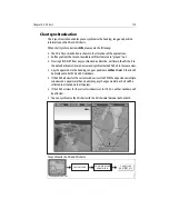
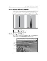
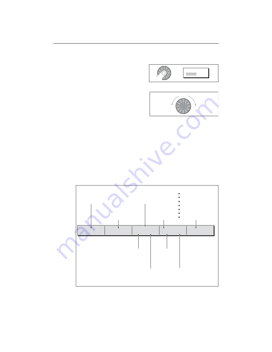
Rotating and pitching


Select

Toggle control between the rotate and 
pitch functions.

Adjust


Turn the rotary control to adjust the active 
function:

• Rotate - rotates the view 0-360

0

.

• Pitch - changes the vertical angle of 

view. (1-90 degrees)

Note: 

The rotary control is always active to adjust pitch/rotation (even when the soft 

key sub-menus are displayed, except when adjusting exaggeration).This is different to 
most other uses of the rotary, which require you to press a soft key to enable adjust-
ment.

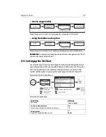
5.7 Other 3D controls

Soft keys

The soft keys control the application as follows:


Press

D8620-1

OR

ADJUST

ROTATE   PITCH

Turn

D8723-1

FIND SHIP

GO TO...

ADJUST ON

EYE     CENTER

ADJUST

ROTATE    PITCH

PRESENTATION...

D8053_2

To find your boat and 
reinstate active 
motion mode, forward 
looking chart view.

To select an existing 
route to follow or a 
waypoint to go to.

Rotates or pitches chart 
around center-of-view 
cross.  Useful for close 
up views.

To select center point 
around which the chart 
will move when rotary 
control used.

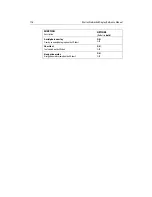
To adjust presentation options:
    Transducer cone
    Depth scale
    Direction of view
    Exaggeration
    Vessel offset
    Declutter
    Waypoint name (ON/OFF) 

To rotate or pitch chart around virtual eye 
point, maintaining a relative position from 
the virtual eye point to the on-screen boat.
Useful for aerial overview.

To change vertical 
angle of view.
(from sea-level to a 
full top-down aerial). 

To select how 
rotary control 
adjusts view

To rotate chart
(0-360

o

). 

Summary of Contents for E120W

Page 1: ...E Series Networked Display Reference Manual Document number 81244_2 Date March 2006...

Page 2: ...r software included herein or parts thereof W3C SOFTWARE NOTICE AND LICENSE http www w3 org Consortium Legal 2002 copyright software 20021231 1 The full text of this NOTICE in a location viewable to u...

Page 3: ...ng or use It is the user s responsibility to exercise common prudence and navigational judgement This device should not be relied upon as a substitute for such prudence and judgement WARNING Product i...

Page 4: ...or disconnect the GPS antenna from the display unit whilst power is switched on Doing this may result in irreparable damage CAUTION UV Light ToprovideprotectionagainstthedamagingeffectsofUVlight itisa...

Page 5: ...how to operate your E Series display in conjunction with Navionicscartography Itassumesthatallperipheralequipmenttobeoperatedwithit is compatible and has been correctly installed This manual is intend...

Page 6: ...t your local dealer or visit the Navionics web site Alternatively anywhereinNorthAmericacallNavionicstoll freeon1 800 848 5896 Outside of North America contact your local dealer or Navionics SpA on Ph...

Page 7: ...d E Series only 15 Setting the language date time format and units of measurement 15 Selecting a page set 16 Selecting an application page 16 Selecting an application window 17 Adjusting the display l...

Page 8: ...Moving a waypoint 39 Erasing a waypoint s 40 Changing the default symbol or group 41 3 7 Sorting the waypoint list 42 3 8 Organising waypoints into groups 42 Displaying the waypoint group list 42 Mak...

Page 9: ...ces and bearings 63 from your boat 63 between two points on your chart 63 4 9 Navigating to a specific point 64 Go to an existing waypoint 65 Resetting cross track error XTE 65 Arriving at your target...

Page 10: ...rking with multiple chart views 91 Setting the orientation of the chart 92 Setting the motion mode 93 4 18 Altering the level of chart detail displayed 94 Showing or hiding waypoints waypoint informat...

Page 11: ...Chapter 6 Using the Fishfinder 117 6 1 Introduction 117 6 2 How does the Fishfinder work 117 6 3 What can the fishfinder show me 118 Interpreting the bottom structure 119 Factors influencing target d...

Page 12: ...er operating modes 146 7 4 The radar picture 147 7 5 Marking a position on the radar screen 148 7 6 Changing what you see in the radar window 148 Setting the orientation of the radar 148 Setting the m...

Page 13: ...video application 179 Displaying a video application 179 Customizing the video application 180 Adjusting the image 183 Chapter 10 Using the Course Deviation Indicator 185 10 1 Introduction 185 10 2 T...

Page 14: ...dar 196 Tracking storms 196 Lightning 197 Surface observation stations 197 City forecasts 198 Wind 199 Waves 199 Surface pressure 200 Viewing data at a particular location 200 12 8 Animated weather gr...

Page 15: ...Introduction 211 14 2 What is AIS 211 Classes of AIS data 211 14 3 What do I need to run AIS 213 14 4 Selecting the AIS function 213 AIS status 213 14 5 How is AIS data displayed 214 AIS Target symbo...

Page 16: ...39 16 1 Introduction 239 16 2 Maintenance procedures 239 Servicing and Safety 239 Routine checks 239 Cleaning the display 240 16 3 Resetting the Display 240 Settings reset 240 Settings and data reset...

Page 17: ...display can be transferred between applications and to other SeaTalk instruments within the system For more detail on system integration please refer to the Installation Guide CANCEL OK RANGE IN OUT P...

Page 18: ...pret your surroundings Monitor where you are going Record where you have been Navigate to a specified position waypoint Build and navigate routes View details of nearby features services View details...

Page 19: ...avoidance Navigate to a specified position waypoint View details of boats equipped with AIS VRM EBL GAIN TARGETS DISPLAY PRESENTATION TARGET TRACKING 6nm North Up Relative Motion Rings 1nm D7375 2 D73...

Page 20: ...mviaNMEA inordertoreceive this data Waypoints Chapter 3 AIS Chapter 14 Whilst not applications in their own right waypoints and AIS are handled at system level and are covered in separate chapters D74...

Page 21: ...age 262 Once enabled you can use the simulator Before installation Simply connect the display to a 12V DC power supply fused at 1 amp by attaching the red core from the power lead to positive and the...

Page 22: ...6 E Series Networked Display Reference Manual...

Page 23: ...Powering the display ON OFF Power ON Press the POWER button until the introductory logo is displayed The keys light up and after a few seconds an application page and a navigation warning and weather...

Page 24: ...and hold to maximise current window Press again to return to multiple windows PAGE Press to scroll through available pages Press and hold to select different page set or customise your own layout WPTS...

Page 25: ...IT DETAILS EDIT DEFAULT SET UP DEFAULT SYMB GROUP D7364 2 WPTS MOB PAGE ACTIVE MENU DATA Example The example above shows the series of button and soft key presses required to change the waypoint defau...

Page 26: ...sor labels and their meanings please see Appendix C 2 For details of how to temporarily hide the cursor please see page 236 2 4 Displaying applications The variousapplications that makeup your E Serie...

Page 27: ...re a response e g press ACKNOWLEDGE to silence alarms Pop up messages MARPA ALARM Target lost on screen Data base lists Menus see next page Used to configure system to your particular needs 3nm Head U...

Page 28: ...e menus Setup Radar Setup GPS Status Compass Setup AIS Layer Status System Setup Alarm Setup Display Setup Databar Set Select Page Setup System Diagnostics Remove CF Card D8500_1 Setup Chart Setup GPS...

Page 29: ...r case although the system is not case sensitive e g WAYPOINT 1 Waypoint 1are con sidered to be the same name 2 If you need to use special or accented characters e g the Extended Character Set should...

Page 30: ...ver NO FIX yourunithasbeenunableto connecttoa suitableGPSreceiver The scanner icon indicates the current status of your radar scanner Icon rotates the scanner is transmitting TRANSMIT TX mode Icon sta...

Page 31: ...d E Series system is powered on for the first time an alarm will sound and you will be asked to nominate which display is to be the data master For details of how to change the data master please see...

Page 32: ...onfigured page sets meet your particular requirements and or you intend to use the engine monitor weather or video application refer to the Setup and Customizing chapter for details of how to customiz...

Page 33: ...ge and display the associated soft keys Multiple to single window To make the active window full screen when multiple windows are being displayed Single to multiple windows To return to multiple windo...

Page 34: ...working Day night operation To select the day night mode of operation Thedisplaysavesthecurrentpalettewhentheunitispoweredoff Ifthepalettewasset to NIGHTwhen it was last used and you then power on in...

Page 35: ...able you to get the most from your display Their uses include Detailed cartographic information Obtain detailed cartographic information of the area that you navigate using Nav ionics chart cards To c...

Page 36: ...home 5 To prevent the ingress of water and consequent damage close the chart card door and press firmly until a click is heard Removing a card with the unit powered on 1 Select the CF Card Removal fu...

Page 37: ...lick is heard 2 8 Managing data This section explains how you can manage the data contained in your E Series and includes the following Writing retrieving to a CF card Erasing information from a card...

Page 38: ...Select list containing data for saving 3 Define data for saving ARCHIVE AND TRANSFER SAVE TO CARD DATA D8070_1 Insert card Toggle to required list D8655_1 Contents for selected list displayed SELECT L...

Page 39: ...ge to give you the options of retrieving as new replacing or cancelling the retrieving process ARCHIVE AND TRANSFER RETRIEVE FROM CARD DATA D9094_1 Insert card Toggle to required list D8655_1 Contents...

Page 40: ...ant to delete the item s before it takes place 1 Insert the card and select the ERASE FROM CARD function 2 Select the required list 3 Define data to be deleted ARCHIVE AND TRANSFER ERASE FROM CARD DAT...

Page 41: ...nt access to modification and sight of your waypoint and route databases and functions by means of a password Password confirmation When Password Protection is enabled and you are attempting to access...

Page 42: ...oint Password Setup Select Waypoint Password Setup System Setup Menu System Integration Waypoint Password Setup Setup Radar Setup GPS Status Compass Setup System Setup OK D8962_1 Select ON Select Enab...

Page 43: ...n onepowercycle the system shall display the hint There is no limit to the number of attempts to enter a valid password but if you forget your password you will need to perform a Settings D8958_1 Add...

Page 44: ...etwork System data including user created databases are managed by the data master The display that has been installed and nominated as the master should always be switched on preferably first The mas...

Page 45: ...atabar on off and configuration Ruler settings Postion Mode TD Setup Simulator Bearing Mode MOB Data Type Variation Source Manual Variation Langauge Extended Charactor set Ground Trip Reset Settings R...

Page 46: ...ordingtotheMOBdatatypesetintheSystem SetUp see page 262 Assuming that your boat and the MOB are subject to the sametideand windeffects deadreckoningnormally givesa moreaccuratecourse Radar range chang...

Page 47: ...an specify what alarms will operate and the parameters within which they will sound via the Alarm Setup Menu see page 265 Cancelling alarms Display alarms BypressingtheACKNOWLEDGE softkey thealarmissi...

Page 48: ...32 E Series Networked Display Reference Manual...

Page 49: ...intscanbecombinedtogether to forma route If you havenetworked several E Series Displays any waypoints that are created on one display are seen by all the other displays The details of all waypoints ir...

Page 50: ...On 3D chart and CDI windows a waypoint is represented only when it is active displayed in a box Waypoints on Fishfinder windows When a waypoint is created it is represented on fishfinder windows by a...

Page 51: ...asbeenplaced youcanviewitsdetailsandeditthem ifnecessary For more information see page 37and page 38 at the cursor at your vessel s position Ifthesystemcannotdetermineyourposition awarningisdisplayeda...

Page 52: ...ur boat and the waypoint If required you can display navigation details for the active waypoint in the data bar see page 259 using the cursor To navigate to a waypoint using the cursor when a chart or...

Page 53: ...tails for the active waypoint in the data bar see page 259 using the cursor To view the details of a waypoint that is not active Note Detailsofthewaypointthatyouarecurrentlynavigatingto canbeaccessedv...

Page 54: ...can be edited in a variety of ways You can Change the waypoint details name symbol group or add a comment Move a waypoint Erase a waypoint Change the default symbol and group of newly placed waypoints...

Page 55: ...hods of moving a waypoint by entering new coordinates If you know the new co ordinates bearing or range for the particular waypoint you canenterthisinformationbyeditingthewaypointasdescribedintheprevi...

Page 56: ...its waypoints can still be displayed If you attempt to erase a waypoint from a hidden route a warning message will be dis played 2 For details of erasing groups of waypoints see page 45 Erasing an in...

Page 57: ...he default Foranalternativegrouptobeselectedforthedefault itmustfirstbecreated see page 43 1 Select either the default symbol or group 2 Change the symbol or group default D8716 1 ARCHIVE AND TRANSFER...

Page 58: ...allwaypointsareautomatically placed in the default My Waypoints group when they are created In order to make your waypoints easier to manage you can organize them into groups of your choice Whenfishin...

Page 59: ...S WAYPOINT GROUPS Deep fishing Shallow fishing Reef fishing GROUP LIST e g D8293_1 MAKE NEW GROUP OK D8293_1 MAKE NEW GROUP OK Or EDIT GROUP NAME OK Edit name Save MAKE NEW GROUP MAKE NEW GROUP OK Mak...

Page 60: ...whilst editing press CANCEL D8298_1 OK Fishing GROUP LIST My Waypoints Waypoint 1 Waypoint 2 Waypoint 3 MOVE BETWEEN GROUPS GROUP A GROUP B SELECT GROUP B My Waypoints Deep fishing Shallow fishing Ree...

Page 61: ...3 9 Controlling waypoint display When you have placed many waypoints on your system it may become difficult to easilyinterpretchartorradarinformation Thisisparticularlythecaseifyouhavemany waypointsi...

Page 62: ...theradar and chart applications 1 Display the SHOW BY GROUP function 2 To change the status show or hide of a waypoint group Note Waypoints in an active route are always displayed regardless of wheth...

Page 63: ...ing data from your boat s Global Positioning System GPS 2 Your E Series Display has a built in world map but to use your Display as a naviga tion aid you will need detailed information for the area yo...

Page 64: ...re the distance and bearing between two points see page 63 Place waypoints at specific locations see page 64 Navigate to a specific point see page 64 Build and follow a route see page 67 Monitor where...

Page 65: ...D CURSOR When motion mode is suspended the mode is shown in the status bar in parenthesis e g RELATIVE MOTION zoom operates about your cursor position Provided the necessary data to ascertain your ves...

Page 66: ...pended see page 49 and page 93 Panning Panning moves the chart that is displayed to a different area To pan a chart simply press the appropriate arrow left right up down on the trackpad When thecursor...

Page 67: ...ct that is marked on the chart including source data for structures lines open sea areas etc Details of ports port and business services tidal and current information wrecks and obstructions Panoramic...

Page 68: ...Finding nearby features and services You can locate the nearest waypoint port port service tidal and current stations wreck or obstruction to the cursor position 1 Select position for the FIND NEAREST...

Page 69: ...iamond 1 To display numerical tidal information You can now view additional tidal data 2 To display additional tidal data including a tidal curve D8310_1 FIND FIND NEAREST WAYPOINTS PORT SERVICES TIDE...

Page 70: ...current curve You can now Move the time selector using the trackpad rotary control Change the displayed date using the soft keys Displaying details of port services You can display details of port ser...

Page 71: ...W ON CHART D8314_1 OK SEARCH BY NAME EDIT NAME D 8309_1 SEARCH BY NAME Enter Port Name GA Enter port name or part of using OK or Soft key SEARCH D8742_1 SELECT PORT GANDERS MARINE GANDERS BASIN Positi...

Page 72: ...Utilities Banks Restaurants Bars Supplies Hookups Fuel Services for selected port displayed Select appropriate port symbol D8317_1 Highlight required service Water Transportation Car Services Utiliti...

Page 73: ...Select appropriate port symbol OBJECT INFO RAINBOW MARINA Photos Position 290 58 147N 0930 52 215W Book5 Chp6 Book5 Chp5 Pilot Book D8745_1 OBJECT INFO RAINBOW MARINA Photos Pilot Book Position 290 58...

Page 74: ...the chart This symbol is placed where the photo was taken and the angle of the shot is indicated by the camera symbol You can also access the photo from the port services information To display a pan...

Page 75: ...tography Setup Menu or by switching on the DECLUTTER option via the PRESENTATION soft key Business services points of interest symbols Airport Babysitting Barber Bank Camping Car hire Fishing equipmen...

Page 76: ...resolution and the availability of a colored overlay is dependent on the region covered by the chart card Note Ifanaerialphotooverlayisappliedtoachartwindowthatissettosystemview the overlay will be d...

Page 77: ...rpret deeper water dark blue from shal lower light blue and to view land features simultaneously In shallow water in some parts of the world where the photos are good and clear you will actually see b...

Page 78: ...d your boat View AIS alarm and safety related messages Thisinformation is displayed in the formof an overlay and additional data isdisplayed in a dialog box on your 2D chart screen e g To switch on AI...

Page 79: ...therefore only affect the individual window on which you are working To position the ruler 1 Position the ruler starting point 2 Position the ruler end point To reposition the ruler To reposition eit...

Page 80: ...manually you can also use the chart to determine the bearing or direction to steer Note If you are currently navigating a route or going to the cursor waypoint you must press STOP GOTO before the sys...

Page 81: ...ypoint list Resetting cross track error XTE When you are following a waypoint you can restart the XTE This results in a new course from the current vessel position to the current target waypoint Resta...

Page 82: ...By selecting Auto Range mode your chart will automatically adjust the range to maintain both your boat and the target waypoint on screen using the largest scale possible To select Auto Range mode Note...

Page 83: ...used to navigate a course A route is displayed on screen as a series of waypoints linked by a line If you have a network of E Series Displays routes are shared across all the Displays What can I do wi...

Page 84: ...n include a waypoint morethan oncein a route but thesame waypoint can not be placed consecutively You can create a new route when the route list is full but on saving this you will be prompted to choo...

Page 85: ...ur route when it is complete see page 71 for details Building a route using the waypoint list You may prefer to build routes using existing waypoints in the waypoint list 1 Select the Waypoint List ro...

Page 86: ...ndo the last waypoint on screen route build only Delete a waypoint from the new route list waypoint list route build only Abandon the route build Undoing the last waypoint To remove the last waypoint...

Page 87: ...Route Or Save the built route for later use and rename it if required Quick routes A route that is saved and immediately followed is referred to as a Quick Route If a Quick Route already exists it is...

Page 88: ...sounds seepage 65 Oncethe alarm is acknowledged the next waypoint is selected the display updates to indicate the next leg of the route and the system sends the new navigation data to the autopilot Th...

Page 89: ...hefirst andrenumbersthewaypointsaccordingly Theroutenamemovestothe reassigned first waypoint and then the system automatically activates the reverse follow route function Note To stop following an act...

Page 90: ...in a new course from thecurrent vessel position to the current target waypoint Restarting XTE is useful if you find yourself off track and want to go straight to your target rather than get back onto...

Page 91: ...ently being navigated to active the data is updated to show bearing distance and time from your current position via the route list 1 Display the Route List 2 Display details of the selected route wit...

Page 92: ...comes the target then the system shall cancel the edit the waypoint shall remain in its original position Selecting a route for editing For a route to be edited it must first be selected either via th...

Page 93: ...using the appropriate soft keys not applicable when adding a waypoint at the beginning of a route Note You will not be able to edit the waypoint that you are currently navigating to target waypoint Ad...

Page 94: ...l to Waypoint column Select waypoint for insertion Make Route Waypoints Harbour Ent Midchannel Outer Harbour Waypoint 4 500 16 75N 0010 6 095W 500 47 356N 0010 6 604W Pierhead Sunday tour 01 Midchanne...

Page 95: ...ee page 76 2 Select the amend route course option 3 Define new or existing waypoint D8373_1 INSERT WAYPOINT PLACE WAYPOINT Move cursor over appropriate leg of route Stretch to position for new waypoin...

Page 96: ...can remove a waypoint from within a route provided that it has not been used in anotherroute Ifyoutrytoremoveawaypointthatisusedinanotherroute thesystem will warn you that it cannot be removed D8381_1...

Page 97: ...anewQuick Route Erasing a route You can delete any route in your system except for the one that you are following When you erase a route the system deletes only those waypoints created with this parti...

Page 98: ...ermined by thedistanceyour boat will travel in the time youhavespecified 3mins 6minsorinfinite intheChartSetupMenu seepage 98 at the current speed Any times that you specify will apply to all chart vi...

Page 99: ...arm clock and Temperature Navigation alarms Arrival and Off track Radar alarms Guard zones Fishfinder alarms AIS alarms Weather alarms When an alarm is triggered a buzzer sounds and a pop up window de...

Page 100: ...nge synchronization Notes 1 Radar range synchronization is not available when the chart motion mode is set to Autorange 2 The2Dchartcanbesynchronizedwitheitherthe3Dchart seepage 113 or the radar but n...

Page 101: ...me of the radar options and if a radar is connected the radar image will be overlaid on the chart e g 2 To access radar and navigation options Note Ifradaroverlayisappliedtoachartwindowthatissettosyst...

Page 102: ...If RDR RNG SYNC is set to ON see page 84 the chart scale also changes 4 15 Recording where you have been What is a track A track is an on screen trail that represents the course you have taken This t...

Page 103: ...ge 98 Specify the distance between each track point see page 98 Creating a track To start a track If the power fails whilst a track is being recorded or the position fix is lost a break will occur in...

Page 104: ...egment is converted to a route CAUTION Beforefollowingtheroute ensurethatitissafefornavigation noting thatit may deviate from your actual path travelled from the current track You can create a route f...

Page 105: ...track for editing For a track to be edited it must first be selected either via the track list or by selecting the appropriate track on screen D8368_1 CREATE ROUTE FROM TRACK YES NO Route generation...

Page 106: ...ous tracks in your system 1 Select the appropriate track for editing see page 89 2 Select the Edit Name or Edit Color option 3 Edit and save Erasing a track You can delete any track in your system 1 S...

Page 107: ...hared across networked E Series displays System chart view When a chart application is started it defaults to system view Any windows set to system view will have the same presentation as other system...

Page 108: ...tes accord ingly Notes 1 To prevent continuous backwardsand forwards rotations asthe boat yawsfrom side to side the chart will not update unless the heading changes by at least 10 degrees from thelast...

Page 109: ...range in autorange also suspends motion mode The default setting is relative motion with zero offset The mode that you select is restored at power up When a chart window is set to SYSTEM view the moti...

Page 110: ...orientation isset to Head Up Autorange Autorange selects and maintains the largest possible scale of chart that will display both the boat and the target waypoint Autorange is not available if radar c...

Page 111: ...which you are working Show hide by group symbol You can show or hide waypoints with a particular symbol or belonging to a specified group 1 Select to show hide by waypoint group or symbol 2 Change st...

Page 112: ...routeortrackappliedtoachartwindowthatissetto system view will be displayed in all other system view chart windows using the cursor You can use the cursor method to hide a route or track Note Use the r...

Page 113: ...ss services if available on your cartography To declutter your chart If the declutter option is applied to a chart window that is set to SYSTEM view the declutter will be applied to all other system v...

Page 114: ...ct Information OFF No info pop up is displayed but detailed data can still be dis played by pressing OK ALL ON the info pop up for all cartographic areas including objects is displayed PointsON theinf...

Page 115: ...ition errors in the cartography This adjustment is indicated as a distance north west ve or south east ve from your vessel position to a maximum of 1000m To view the effects of an offset you can turn...

Page 116: ...g the offset value To change the offset value 1 Select the Chart Offset function see previous section 2 Set the north south offset value 3 Set the east west offset value Resetting the offset value To...

Page 117: ...e g place names etc ON OFF Chart Boundaries The line indicating the boundary of the chart ON OFF Spot Soundings Number on the chart indicating depth ON OFF Safety Contour Areaswithdepthsshallowerthat...

Page 118: ...seabed points tide station current stations and port information ON OFF Land Features The cartographic features that are displayed on the land ON OFF Colored Seabed Areas In available areas e g Portu...

Page 119: ...ght and in clear weather conditions The simulator mode can also be used to help you gain experience It is strongly recommended that before you use your 3D chart application you read and understand Cha...

Page 120: ...n is new to you or visibility is poor 3D cartography can helpto give you the confidence to know where you are and what is around you As with a conventional chart active waypoints and routes can also b...

Page 121: ...a similar way to a 2D chart To move around the 3D chart and displaythearearequiredattheappropriatescaleandangle usea combinationof panning zooming rotating and pitching Panning Panning moves the 3D ch...

Page 122: ...TATE PITCH Turn D8723 1 FIND SHIP GO TO ADJUST ON EYE CENTER ADJUST ROTATE PITCH PRESENTATION D8053_2 To find your boat and reinstate active motion mode forward looking chart view To select an existin...

Page 123: ...TRE but rotatingor panning the chart will put it into planning mode Planning mode Planning mode enables you to view an area of the chart different to the one in which you are navigating so that you c...

Page 124: ...is pressed the system automatically puts you into active motion mode AFT PRT PRT ROTATE 106oT 2 431nm Eye point above and to starboard side of boat looking to port STB ROTATE 280oT 2 431nm AFT D8726_...

Page 125: ...art from different angles Views of up to 4 different areas of the chart Note For full details of page set up and active windowsrefer to page 17 Vessel offset Youcanspecifywhethertheboatisfixedinthecen...

Page 126: ...a colored overlay is dependent on the region covered by the chart card Aerialphotooverlayiscontrolledviathe3DChartSetupMenu See page 115formore details 5 11 Making the view clearer You can make the v...

Page 127: ...on your chart view level it can make features or even your position difficult to see Declutter helps you to reduce this confusion and make the chart clearer by removing some objects from view To declu...

Page 128: ...of how to set up a page set to view the two applications together see page 17 3D view locator If required you can show the 3D view locator on the 2D chart This is a polygon outlined in blue and extend...

Page 129: ...vemotion modeviewandsynchronizethe2Dcharttothesame view Anychangesmadetotheheading rangeorpositionineither2Dor3Dchartswill be displayed in both 2D and 3D windows If the2Dchartview forthecurrentwindow...

Page 130: ...eful when fishing as it enablesyoutocomparethechartviewwiththeinformationyourfishfinderisshowingyou To display the transducer cone 5 14 Navigating with 3D charts You can access navigation options when...

Page 131: ...become more familiar with the system Any settings that you change are retained at power off To select the 3D Chart Setup Menu This menu lets you change FUNCTION Description OPTIONS Default in bold Ce...

Page 132: ...nce Manual Aerial photo overlay Overlay an aerial photograph on the 3D chart ON OFF Chart text Text viewed on the 3Dchart ON OFF Navigation marks Navigation marks viewed on the 3Dchart ON OFF FUNCTION...

Page 133: ...ency and adjusting the gain values Note Please refer to the Installation Guide for fishfinder calibration information 6 2 How does the Fishfinder work The fishfinder application uses a Digital Sounder...

Page 134: ...indicating fish A status bar noting the frequency and gain settings The bottom depth You can customize the fishfinder to Hide the depth of the targets see page 128 Show the depth lines see page 135 C...

Page 135: ...nder provides various features to help you interpret the fishfinder picture Factors influencing target display The shape and size of this mark is influenced by a combination of factors Boat speed The...

Page 136: ...than the fish or bottom echoes your fishfinder picture may be impaired by echoes received from floatingor submerged debris air bubbles or from your boat smovements Thisisknownasbackgroundnoiseorclutte...

Page 137: ...ng A Scope automatically switches OFF Bottom Lock and Zoom D6674 3 MODE 1 The A scope image is centred in the window MODE 2 The left hand side of the Mode 1 image is expanded to give a more detailed v...

Page 138: ...to range in out on the image up to the maximum depth displayed on the scrolling bottom and A Scope images Changes to the range are reflected in all Fishfinder windows To select manual auto range mode...

Page 139: ...ses the area showninthe zoom window also increases Selecting a split or full screen zoomed image You can either replace the standard fishfinder image with the zoomed image ZOOM ON or split the screen...

Page 140: ...When the zoom function is selected the system automatically selects the zoom position so that the bottom details are always in the lower half of the display If required you can reposition the portion...

Page 141: ...age was displayed selecting Bottom Lock automati cally switches OFF A Scope and Zoom Adjusting bottom lock range position Adjustingtherangeofthebottomlockimageallowsyoutoviewmorebottom details You can...

Page 142: ...ation of features mud sand fish targets etc with various sonar signal strengths White line When this feature is applied a white lIne is drawn along the bottom as defined by the digital depth value and...

Page 143: ...eed scroll 100 Automatic The system automatically adjusts the scroll speed based on boat speed Less than or equal to 0 5 kts scroll speed is constant at 10 Between 0 5 15 kts scroll speed varies linea...

Page 144: ...h etc When in automatic frequency mode and the depth changes the new frequency will NOT be paused To pause or resume scrolling Changing how the depth digit is displayed The depth under the boat is dis...

Page 145: ...ine labelled WPT see illustration below is displayed on screen You can edit waypoints and navigate to them in the Fishfinder window Notes 1 For full details of working with waypoints please refer to C...

Page 146: ...ctly linked to the Fish Alarm sensitivity the greater the fish alarm sensitivity the greater the number of labelled returns These targets are switched on off via the Fishfinder Display Setup menu see...

Page 147: ...idually Note VRMs set up in Fishfinder are unrelated to those set up in Radar 1 Select the VRM option 2 Pause the display to make it easier to position the VRM over an object see page page 128 3 Measu...

Page 148: ...hanged from the standard configuration to suit your particular needs The Fishfinder Setup Menu is divided into three sections Display settings Transducer settings DSM settings To select the Fishfinder...

Page 149: ...s are displayed N B The level of targets displayed is directly linked to the level of Fish Alarm sensitivity see page 267 ON OFF Depth Lines Controls whether horizontal lines indicating depth are disp...

Page 150: ...E Series then allows you to select an appropriate transducer from the 600W or 1kW list 600W detected P65 66 P79 P319 B117 SS555 B66V B66VL B744V b744VL SS544V B45 1kW detected B256 B260 R99 Select Sp...

Page 151: ...R Interference Rejection Removes spikes caused by other fishfinder equipped vessels AUTO LOW MEDIUM HIGH 2nd Echo Interference Rejection Minutelyadjuststhepingrateaccordingtothe2ndecholevel Results in...

Page 152: ...rmal mode of operation Manual frequency Manual frequency allows you to manually set the system to either a single or dual frequency mode Single frequency mode This mode sets the transducer to ping at...

Page 153: ...face In a third fishfinder application select BOTH to split the window and display a high resolution image 200 kHz and a wider cone 50kHz simultaneously Usingthesesettingscoversallpossibilitiesandensu...

Page 154: ...s If necessary you can set the gain controls manually The new values remain set even when you switch off the display and are applied to both the active window and any other fishfinder windows displayi...

Page 155: ...ndividual frequencies is only available when the selected frequency isset to BOTH Adjusting the power setting The Power control provides adjustment of the transducer signal Auto This is the default se...

Page 156: ...e Power Setting 1 Select the power setting function 2 Select the power setting mode and adjust as necessary D8460_1 FISHFINDER SETTINGS POWER Press to highlight AUTO D8461_1 Select required mode POWER...

Page 157: ...radar at sea is to detectthepresenceofobjects knownas targets atadistance andiftheyaremoving detect their speed This chapter of the Reference manual provides the information and instructions to enable...

Page 158: ...horizon Factors impairing a radar picture Not all radar echoes are produced by valid targets Spurious echoes may be caused by Side lobes Indirect echoes Multiple echoes Blind sectors Sea rain or snow...

Page 159: ...particularwithlargerobjects Sidelobeechoesformeitherarcson the radar screen similar to range rings or a series of echoes forming a broken arc Indirect echoes There are several types of indirect echoes...

Page 160: ...duction of the beam intensity though not necessarily a completecut off However forwider obstructions theremaybea totallossofsignalin the shadow area There may also be multiple echoes which extend behi...

Page 161: ...ityandposition Thesereturnssometimesappearaslargehazyareas dependingontheintensityofthe rainfall or snow in the storm cell Interference When two or more radar equipped vessels are operating within ran...

Page 162: ...ation Standby STDBY Scanner on but not transmitting and antenna not rotating Antenna does notrotate the scanner does nottransmitand the radar data is removed from the screen This is a power save mode...

Page 163: ...endent on many factors and may not necessarily be proportional to its physical size Nearby objects may appear to be the same size as a distant larger objects With experience the approximate size of di...

Page 164: ...edontheradarscreenviatheWPTS MOBbuttoninthesameway as they are placed on a chart You can edit waypoints and navigate to waypoints in the radar window For full details on using waypoints and passage pl...

Page 165: ...ata becomes unavailable whilst in this mode a warning messagewillbeshown thestatusbarindicatesNorth Upinbrackets andthe radaruses0 heading inrelativemotion When headingdata becomes available once more...

Page 166: ...e a warning message willbeshown thestatusbarindicatestheCourseUpinbracketsandtheradaruses0 headinginrelativemotion Whenheadingdatabecomesavailableoncemore Course Up mode is reinstated To select the or...

Page 167: ...fixed radar targets maintain a constant position andmovingvessels includingyourboat travelintrueperspectivetoeachotherandto fixed landmasses on the screen As the boat s position approaches the edge of...

Page 168: ...g The gain controls sea gain tune FTC and rain The target display controls interference rejection expansion wakes Using the GAIN functions The gain function reduces the effects of false echoes and clu...

Page 169: ...ble On short range scales donotsettheSEAcontrolsohighthatallclutterisremoved sincethiscould stop you seeing echoesfrom close targets The acuteness of the sea clutter curveis setupintheRadarSetupmenu s...

Page 170: ...ed you should turn the FTC function down when its use is not required Since storm cellsareusuallyvisibleforlong distances dueto their extremealtitude you may wish to leave them displayed so that you c...

Page 171: ...expansion to LOW Note Selecting this option may compromise target resolution D8414_1 MENU Setup GPS Status Compass Setup Highlight Radar Setup Select Radar Setup Radar Setup Select NORMAL or HIGH Sel...

Page 172: ...ia the Radar Setup Menu whether these wakes are shown for periods of 10 seconds 30 seconds 1 minute 5 minutes or 10 minutes To specify the wake period Note You can also enter the Radar Setup Menu by p...

Page 173: ...unit depending upon the scanner fitted The range of the radar is adjusted by pressing the RANGE button Press IN to decrease the range scale or zoom in Press OUT to increase the range scale or zooms ou...

Page 174: ...and spacing of the rings changes as you range in and out Using the cursor To measure the bearing and range from your boat to a specified target move the cursor to the appropriate position on the scree...

Page 175: ...a line drawn from your boat to the edge of the window When this line is rotated to align with a target its bearing relative to your boat s heading is measured and displayed on the ADJUST EBL soft key...

Page 176: ...he current range and 030 relative to your boat s head If this setting isadjusted thedisplay will retain the adjustments and use them when the VRM EBL is next turned on 2 Adjust the VRM to the required...

Page 177: ...its new origin to obtain the bearing Floating a VRM EBL 1 Create the VRM EBL as described previously 2 Select the floating option 3 Measure the range between two points 4 Measure the bearing between t...

Page 178: ...Set an alarm to trigger when a target is within a specified zone Guard Zones Display detailed information on tracked targets MARPA Display the identity of other vessels and if broadcasted their voyage...

Page 179: ...sector zones or 360 circular zones Your radar can be set up using one or two zones You can adjust the sensitivity of the guard zone via the Alarms Setup Menu described on page 267 To set up a guard zo...

Page 180: ...zone D9104_1 ZONE SHAPE SECTOR SET INNER xx xx nm Press to highlight Set inner limit for guard zone OK Repeat for other settings 6nm Head Up D6832 2 Circular Guard Zone D6761_3 ZONE SHAPE CIRCLE SET...

Page 181: ...g data will reduce the effect of the other conditions Introduction to MARPA You can use the Mini Automatic Radar Plotting Aid MARPA functions for target tracking and risk analysis MARPA improves colli...

Page 182: ...ing the appropriate soft key will silence the alarm and remove the on screen warning and the target lost symbol How far from my boat does MARPA work MARPA target acquisition is only available at radar...

Page 183: ...ed and vector length set in the MARPA Setup menu To display the CPA graphic and associated soft keys MARPA targets D6810_4 D9008_1 Vector CPA graphic 3 9 D9009_1 CPA GRAPHIC CPA GRAPHIC CPA GRAPHIC 18...

Page 184: ...ameter Options Default in bold Vector Length The time period specified for drawing length of vectors 0 5min 1 min 3 min 6min 12min 30 min 60 min Target History Plots a target s previous position at sp...

Page 185: ...1 Display the MARPA List 2 Cancel target s D6829 2 TARGET TRACKING Move cursor over target to be acquired Target D8806 1 ACQUIRE TARGET Target being acquired symbol displayed If target present for se...

Page 186: ...AIS on a radar window For more information on AIS refer to Chapter 14 Automatic Identification System AIS 7 11 Setting up your radar The set up for your radar can be changed from the standard configu...

Page 187: ...scans 30 scans Standby Period Indicatesthe number of minutes that the system shuts down the scan ner does not rotate and the display is in standby mode 3 minutes 5 minutes 10 minutes 15 minutes Sea C...

Page 188: ...alarms Data alarms External SeaTalk alarms When an alarm is triggered a buzzer sounds and a pop up window describing the alarm and how to clear it is displayed To switch these alarms on off and set th...

Page 189: ...m or by instruments available on NMEA or SeaTalk 8 2 Selecting a data application To select a data application 1 Select a page set that includes a data application 2 Select a page which includes a dat...

Page 190: ...ecttheindividualdis play on which you are working Pre configured data panels The pre configured data panels include data associated with Navigation Waypoint Route Fishing or Sailing To select a pre co...

Page 191: ...ch data item Note YoucanalsoconfigurethedatapanelsinthiswayintheEngineMonitoringand CDI applications Renaming a panel Youcancustomizethenamesofthepanelsasrequirede g theSAILINGpanelcouldbe renamed RAC...

Page 192: ...tion in which the selected cell can be split is indicated on the soft key 2 Split the highlighted cell D9106_1 Data Groups Vessel Navigation Depth Wind Time and Date Engine Environment Highlight data...

Page 193: ...Heading 2960 T Speed 20 0kt Cell for splitting selected e g e g Cell splits vertically Soft key indicates direction of split Split horizontally Split vertically OR D9107_1 NAVIGATION Press and hold r...

Page 194: ...178 E Series Networked Display Reference Manual...

Page 195: ...application to cycle the display of each video input You can also adjust the brightness contrast color and aspect ratio of the image Note For detailsof how to connect such equipment to yourE Series d...

Page 196: ...ting the input source type Your Display is supplied with cabling to connect to a composite input source If your camera DVDetc usesS Videoinput youwillneedtopurchaseandfittheappropriate cabling in the...

Page 197: ...changes that you have made are reflected in the Video Setup Menu and on the video application s soft keys e g D8486_1 OK x2 Video 2 mirrors your choice for Video 1 and can no longer be selected indep...

Page 198: ...p the cycle period By default the cycle period is 10 seconds This can be changed 1to 99 seconds if required To specify the number of seconds between shots in the cycle 1 Open the Video Setup Menu as d...

Page 199: ...r each input source If an image appears distorted squashed or stretched you should override this automatic setting and select the appropriate aspect ratio manually 4 3 standard format or 16 9 wide scr...

Page 200: ...184 E Series Networked Display Reference Manual...

Page 201: ...ata 10 2 The CDI screen The CDI gives a graphical representation of yours boat s course in a rolling road format The rolling road represents a width of sea equal to the Cross Track Error XTE limits th...

Page 202: ...same data is dis played in each 2 Select a page which includes a CDI window Once the CDI application is displayed no use is made of the soft keys You will therefore need to open a radar chart or fishf...

Page 203: ...nt of these panels and or the layout of the individual data boxes is not suitable you can configure the system to display the data and layout of your choice see page 175 11 2 Displaying and setting up...

Page 204: ...Panel Setup Menu Configure ENGINE Configure ENGINE FUEL Configure FUEL RESOURCES Configure ENGINE RESOURCES Configure TWIN ENGINE Maximum tachometer range AUTO Select Number of Engines Highlight Numb...

Page 205: ...efore only affect the individual display on which you are working 11 5 What should I do when an alarm is triggered Yourenginemonitorapplicationwilltriggeranalarm viaNMEA SeaTalk2 anddisplay an enginea...

Page 206: ...190 E Series Networked Display Reference Manual...

Page 207: ...incomplete and erroneous information and assume complete responsibility and risks associated with this device and accordingly release Raymarine Sirius Satellite Radio Inc andWSICorporationfromanyanda...

Page 208: ...ather application does not appear in the pre configured page sets You will therefore need to customize a page set to include a weather application window Please refer to page 257 for details Specifyin...

Page 209: ...Note As resolutionin thedata is lost when you zoom out a longway you shouldzoom into display more detail To re centre the map on your boat use the FIND SHIP soft key 12 6 Placing waypoints The waypoin...

Page 210: ...s grey Surface observation stations pink Lightning Wind Sea surface temperature green yellow orange Weather symbols Surface pressure 26 22 22 24 Squall line red D8613_1 Hurricane Category 1 5 Tropical...

Page 211: ...ght pink Dark pink Rain Rain Rain Rain Rain Rain Rain Snow Snow Mixed Mixed 15 19 dBz 20 29 dBz 30 39 dBz 40 44 dBz 45 49 dBz 50 54 dBz 55 dBz 5 19 dBz 20 dBz 5 19 dBz 20 dBz Intensity Precipitation t...

Page 212: ...nes typhoons and super typhoons The system displays the track the storm has taken its current and forecasted position the wind radii current position only direction and speed of travel o D8570_1 Trans...

Page 213: ...ervation stations Hurricane Category 2 OK for more info OBJECT INFO Storm name Storm ID Storm Type Direction Speed Max Wind Speed Max gust Speed Pressure Date Time Position Tropical Storm Data EPSILON...

Page 214: ...ame Station Type Latitude Longitude Time Date Air Temperature Horizontal Visibility Vertical Visibility Sea Level Pressure 3 Hour Pressure Change Pressure Tendancy Wind Direction Wind Speed Peak Wind...

Page 215: ...int see page 200 2 For details of how tochange the windsymbol please refer to page 205 Waves This option displays the current wave height in 16 levels e g For details of how to view actual wave data a...

Page 216: ...ion To setup the animated weather graphic for forecasting wind wave or surface pressure or for the weather radar history loop D8651_1 Squall line red High pressure blue High pressure red Cold front bl...

Page 217: ...ed thePAUSE option has not been selected Ranging panning will cause the animation torestart 2 TheanimationwillbeswitchedtoOFF whenevertheACTIVE PAGE DATA WPS MOB MENU are pressed or when the animation...

Page 218: ...hore Forecasts and High Seas Forecast or Great Lakes Forecast and Near Shore Forecast or Canadian Coastal Weather Forecast To display marine zone forecasts 1 Select the MARINE ZONE FORECASTS option 2...

Page 219: ...s ACKNOWLEDGE The alert is removed from the display The watchbox warning can still be viewed via the Weather Reports soft keys Note Ifrequired youcanswitchoffthemarinewatchboxalarm viatheWeatherSetupM...

Page 220: ...s valid are highlighted on the weather map as a red polygon To show hide watchboxes Displaying watchbox data To display the data relating to a particular watchbox D8608_1 Watchbox alert warning area W...

Page 221: ...the Weather Setup Menu To select the Weather Setup Menu Weather Setup options Showing hiding marine watchboxes and zone boundaries By default your weather application displays marine zone boundaries...

Page 222: ...l Problem Reason Boat symbol not displayed No position fix On start up weather map stays in last view and does not re draw No position fix During use weather map stays in last view and does not re dra...

Page 223: ...nd Japan and areas around the North American continent 13 2 Setting up Navtex weather Before you are able to view Navtex messages you will need to 1 Specify for the communicating NMEA port the baud ra...

Page 224: ...messages that you do not need Sorting the message list Selecting message alert categories On initial power up the system provides alerts for all message categories listed in the Navtex Alert Menu If...

Page 225: ...ert Menu B Meteorological warnings ON C Ice reports ON D Search and rescue information ON E Meteorological forecasts OFF F ilot service messages OFF G Decca messages OFF H Loran messages ON I Omega me...

Page 226: ...210 E Series Networked Display Reference Manual...

Page 227: ...radar application as it can operate in radar blind spots and can detect smaller AIS fitted vessels WARNING Smaller vessels do not have to be fitted with AIS and whilst it is mandatory for larger comme...

Page 228: ...sign IMO number Length and beam Antenna loctation Draft Cargo information Destination ETA Other relevant information Time Ship s position COG SOG Gyro heading Rate of turn Navigational status Dynamic...

Page 229: ...y an AIS icon in the transducer data box You will now need to specify the 38 400 baud for the NMEA port that communicates with the AIS transceiver or receiver see page 230 14 4Selecting the AIS functi...

Page 230: ...dangeroustargets page 220 AIS Target symbols D9056_1 097 T 11 6kt 1 237nm 00h04m33s Safety critical data Heading Large vessel Direction of turn Small vessel Sleeping target Dangerous target flashes Sa...

Page 231: ...ding and direction of turn indicator To switch the AIS VECTOR option ON OFF When a target is activated its symbol is scaled according to the size of the vessel Note The sametarget vector and safe zone...

Page 232: ...idancedata forthe highlighted target To display the AIS List Viewing full AIS data TodisplaydetailedAISdataforanindividualtargete g staticanddynamicandvoyage related data D9092_1 D9091_1 AIS OPTIONS T...

Page 233: ...d the dangerous target alarm can be disabled Once disabled any dangerous targets that are detected will turn red and flash but the alarm will not sound and the pop up will not be displayed The AIS sta...

Page 234: ...nal has not been received for 20 seconds Your AIS receiver generates local alarms which are displayed and sounded on your E Series display whenever an alarm condition exists on the unit Parameter Opti...

Page 235: ...local alarm This list can either be accessedviatheAISLayerSetupMenu seepage 220 orfromtheAlarmsSetupMenu see page 232 Note The local AIS alarms must be acknowledged at the AIS receiver Removing the me...

Page 236: ...be displayed while the simulator is switched on 14 9AIS Layer Setup Menu The AIS Layer Setup Menu allows you to Select the target types displayed ALL or DANGEROUS Switch the display of AIS safety mes...

Page 237: ...nononepage one to view a large scale chart the other for a detailed view of your immediate surroundings Ifnoneofthesemeetyourparticularrequirementsyoucaneditthepagesetstodisplay the application and pa...

Page 238: ...aid on soft keys associated with pages set to OFF Rename a page set If required you can customize the names of the page sets 1 Display the Select Page Set Menu as described on page 221 2 Rename the pa...

Page 239: ...t the right hand side of your screen or horizontally across the top To change the data bar position Data bar size When the data bar is positioned at the top of your screen you have the option of displ...

Page 240: ...velocity made good VMG Wind Waypoint velocity made good VMG Wpt Log trip Log Trip Ground Log Trip 1 Ground Log Ground Trip 1 Ground Trip 2 Ground Trip 3 Ground Trip 4 Rudder NAVIGATION Cross track er...

Page 241: ...tor is switched off the ground log and trip counters resume Selecting the configure options To select the configure options for the data bar ENVIRONMENT Pressure Air temperature Air Temp Sea temperatu...

Page 242: ...data Onceyou haveselected the configure option seeabove you can removedata within the bar D8278_1 OK Data Groups VESSEL NAVIGATION DEPTH WIND TIME AND DATE CURSOR POSITION TRANSDUCER STATUS ENVIRONMEN...

Page 243: ...GPS and Compass setup The options that are available depend on what is connected to your system System wide menus These menus control functions throughout the system When you first power on your disp...

Page 244: ...urse Dead Reckoning Position Variation Source This allows you to compensate for the naturally occurring off set of the earths magnetic field When set to AUTO the value the system would use or is using...

Page 245: ...nt Password Set up Allowsyoutosetupapasswordtoprotectaccesstoyourway point and route databases See page 25 MENU ITEM OPTIONS Default in bold Date Format Displays date as day month year or month day ye...

Page 246: ...r Enabled Disabled Data Master WhensettoON thedisplayyouareworkingonisdefinedas the master ON OFF Bridge NMEA Heading UsedtopreventNMEAheadingdatabeingbridgedontothe SeaTalkbus Switchthisfunctionoffif...

Page 247: ...e menu options will be available on all displays Navtex and AIS are available simul taneously SeaTalk2 Keyboard When connecting a SeaTalk2 keyboardto your systemselect ALL or ONE When ONE selected pre...

Page 248: ...istanceUnit Timer Switches the countdown timer alarm on or off OFF ON Timer Period IftheTimerissettoON thesystemcountsdownfromthetimeyou specify An alarm is triggered when zero is reached 00h01m 99hrs...

Page 249: ...N analarmistriggeredwhen the XTE for any current navigation exceeds the value that you have specified 0 3nm 0 01 9 99nm or equivalent in the selected Distance Unit MENU ITEM OPTIONS Default in bold Gu...

Page 250: ...below the value you specify 5ft 0002ft maximumrangeof transducer Deep Depth Alarm Switches the deep depth alarm on or off If a DSM is not connected this cannot be set OFF ON Deep Depth Alarm Value If...

Page 251: ...rcumstances the figure should be in the region of 1 0 Selecting the satellite differential system You should select the satellite group s appropriate to your area via the Other Set Up soft key WAAS Un...

Page 252: ...When instructed to align heading Display Setup MENU OPTION OPTIONS Default in bold Soft key Autohide Controls whether the soft key bar is automatically hidden if not used for a period of 10 seconds Pr...

Page 253: ...s of how to reconfigure the page sets please see page 221 System Diagnostics This sub menu is for diagnostic use by authorized dealers Remove CF Card This sub menu allows you to safely remove the Comp...

Page 254: ...238 E Series Networked Display Reference Manual...

Page 255: ...ds These can cause adjacent pieces of electrical equipment to interact with one another with a consequent adverse effect on operation In order to minimize these effects and enable you to get the best...

Page 256: ...3 Resetting the Display You can reset the E Series Display in several ways Settings reset Settings and data reset Settings reset All system set up menus including page sets and the data bar are reset...

Page 257: ...required to restore normal operation If afterreferringtothissection youarestillhavingproblemswithyourDisplay contact your local dealer national distributor or Raymarine Technical Services Department...

Page 258: ...mage or corrosion Check SeaTalk High Speed switch or Crossover Coupler correctly connected see Installation Guide How do I upgrade my Display software Visit www raymarine com and click on Support to d...

Page 259: ...compatibility Ensure all Displays have the same software installed see page 237 Problem Solution How do I upgrade my DSM software Visit www raymarine com and click on Support to download the latest s...

Page 260: ...patible message Check software revisions by contacting your local Raymarine dealer Invalid scanner software Version xx x Version xx x required Incorrect software version installed Contact your local R...

Page 261: ...sts are available to answer questions about installing operating and trouble shooting all Raymarine products D8665_1 MENU Setup Highlight System Diagnostics menu Select System Diagnostics menu System...

Page 262: ...rassistance Thedealerisbestequippedtohandleyour service requirements and can offer timesaving help in getting your equipment back into normal operation If repairs cannot be obtained conveniently produ...

Page 263: ...t Navionics customer support If you wish to file a report of an error or omission on a Navionics chart please provide the information to Navionics web site Discrepancy Report section at the link below...

Page 264: ...E Series Networked Display Reference Manual For Sirius weather For questions about the Sirius weather service please contact Sirius directly through their web site www Sirius com or call 1 800 869_54...

Page 265: ...mental Operational Non opera tional temperature range Humidity limit WaterprooftoCFR46 IPX6 suitableforexternalmounting 10 C to 50 C up to 95 at 35 C non condensing Controls 9 defined keys 5 soft keys...

Page 266: ...rations Network Supports 8 devices displays Waypoints 1200 waypoints entered via cursor lat lon range and bear ing from present position or at boat s position 16 character name can be assigned Waypoin...

Page 267: ...lash cards SmartRoute to create a route from track history Track History 10trackswithupto1000pointsineachcanbestoredinthe units internal memory Track optimization reduces number of points used or user...

Page 268: ...erformance limited by scanner type and position Range Ring Accuracy Better than 1 5 of the max range scale in use or 22m 72 ft whichever is the greatest Bearing accuracy 1 Variable Range Markers 2 x V...

Page 269: ...available OFF Timed TX Rotation periods 10 20 or 30 scans Repetition periods 3 5 10 or 15 minutes AIS overlay Switch AIS symbols on off Display heading speed vectors and ROT View detailed AIS data saf...

Page 270: ...cal data Panel type 5 panels available Pre defined engine engine and fuel fuel resources engine and resources twin engines or triple engine support or user configured Data available Tacho boost pressu...

Page 271: ...VTG BWC BWR RMA RMB RMC XTE VHW HDG HDM HDT DBT DPT APB VLW MWV WPL RTE DSC and ZDA Selectable to 4800 4800 Navtex 9600 Navtex or 38 400 AIS NMEA Output User selectable APB BWC BWR DBT DPT GGA GLL MTW...

Page 272: ...256 E Series Networked Display Reference Manual...

Page 273: ...ect current nm Nautical mile DSC Digital selective calling NMEA National Marine Electronics Association DSM Digital sound module N up North up orientation EBL Electronic bearing line OSH Automatic off...

Page 274: ...tworded Display Reference Manual TVG Time variable gain VRM Variable made good TX Transmit WPT Waypoint UTC Universal time constant XTE Cross track error VMG Velocity made good Abbrev Description Abbr...

Page 275: ...CTR Centre of radar Radar FLT Floating EBL VRM Radar GRD Guard zone Radar HDG Heading vector Chart MARPA MARPA target Radar MOB Man Over Board marker Chart and Radar POS Vessel s position Chart RTE R...

Page 276: ...260 E Series Networked Display Reference Manual...

Page 277: ...ther is probably going to be like Front The boundary between two masses of air with different tempera tures i e a mass of cold air and a mass of warm air High Alsoknownasan anticyclone anareaofhighair...

Page 278: ...ing escape routesarecutbyrisingwater3 5hoursbefore arrivalof thecen tre of the hurricane Flooding near the coast destroys smaller structures with larger structures damaged by battering from floating d...

Page 279: ...the ground and a storm cloud Low Also called a depression this region of low pressure can mean wet weather it is the opposite of high pressure or anticyclone Low Pressure A mass of air that presses d...

Page 280: ...organized system of strong thunderstorms with a defined sur face circulation and maximum sustained winds of 39 73 mph 34 63 kt Tropics An area on the Earth s surface that lies between 30 north and 30...

Page 281: ...16 opaqueness level 60 overlay area 61 Aft view 108 Air temperature in data bar 225 AIS alarms 218 active 219 list 234 local 218 classes of data 211 collision avoidance 216 displaying data 213 full AI...

Page 282: ...94 B Bearing alignment 171 measuring 157 mode 228 for EBLs 152 Blind echoes 142 sectors 144 Boat position 50 105 symbol 50 105 115 Bottom fill 126 image 118 lock 125 Bridge NMEA heading 230 Business s...

Page 283: ...ext 101 tide information 82 tracks create route from track 88 create track 87 definition 86 edit 76 89 vectors 82 viewing the chart 49 views 90 local 91 multiple 91 system 91 waypoint arrival alarm 83...

Page 284: ...t 134 ranges 139 reading 130 safety contours 101 shallow alarm 132 spot soundings 101 target ID 130 133 Detecting targets 141 Dialog boxes 11 editing 13 Digital data application selecting a panel 173...

Page 285: ...olor gain 138 palette 133 combining with 3D chart 113 cursor depth 130 deep alarm 132 depth cursor 130 digit 128 133 lines 130 133 offset 134 reading 130 target ID 130 display description 118 DSM rese...

Page 286: ...es 143 Integration 1 Interference rejection 155 171 2nd echo 135 SONAR interference rejection 135 K Key beep 236 Keyboard SeaTalk2 231 L Land features 97 102 Language 15 228 Light sectors 97 102 Light...

Page 287: ...e chart 50 around the weather map 193 waypoint 39 within a group 80 90 waypoints between groups 43 Moving objects 84 Multi media cards 19 cautions 19 use of 19 Multi media chart cards see CompactFlash...

Page 288: ...247 US 246 Password protection 25 enabling disabling 27 setting up 26 Pausing fishfinder 127 PC archiving information 25 transferring information 25 Photo aerial overlay 59 opaqueness level 60 overla...

Page 289: ...ges 157 motion mode 150 orientation 148 149 overlay on chart 84 picture overview 146 power off on 145 principles 141 rain clutter 154 range 157 rings 151 synchronizing with chart 84 relative motion mo...

Page 290: ...afezone ring 218 Sailboat symbol 115 Saving information to a card 21 Scanner operating modes 145 Scroll 133 pause 127 speed 127 133 Sea clutter 144 153 surface temperature 195 temperature at particula...

Page 291: ...Steering using CDI 185 Storm cast 195 Storms tracking 196 tropical 196 Surface observation stations 197 Surface pressure 199 Symbols AIS targets 214 boat 50 105 115 business services 58 MARPA 166 navi...

Page 292: ...ubleshooting 241 weather 206 True mode CPA vectors 167 motion mode 94 151 wind in data bar 225 Tune radar 153 TVG 138 U Uncertain AIS target 214 Unfloating VRMs EBLs 162 Units measurement 15 setup men...

Page 293: ...p 43 move waypoint between groups 43 rename group 44 show hide 95 in new routes 68 list 37 moving 39 navigate to 35 64 using cursor 36 using the waypoint list 36 using waypoint list 65 with cursor 65...

Page 294: ...ropical 196 surface observation stations 197 surface pressure 199 symbols 193 surface pressure 199 tropical statements 201 troubleshooting 206 watchbox 203 data 204 displaying 203 wave height 200 wave...

Reviews: