background image

Transducers
for
Fishfinders

Owner’s 
Handbook

Document number: 81196_2
Date: August 2002

All manuals and user guides at all-guides.com

all-guides.com

Summary of Contents for E66008

Page 1: ...Transducers for Fishfinders Owner s Handbook Document number 81196_2 Date August 2002 All manuals and user guides at all guides com a l l g u i d e s c o m...

Page 2: ...All manuals and user guides at all guides com...

Page 3: ...in this manual Failure to do so can result in personal injury and or navigational inaccuracies Raymarine products are supported by a network of Authorized Service Representatives For information on R...

Page 4: ...voidable differences between the product and handbook may occur from time to time for which liability cannot be accepted by Raymarine Raymarine is a registered trademark of Raymarine Limited SeaTalk i...

Page 5: ...cer 15 Preparation 15 Installation 16 2 2 Installing the Thru hull Transducer 17 Tools and Material Needed 17 Preparation 17 Installation 22 Installation in a Cored Fiberglass Hull 29 Check for Leaks...

Page 6: ...vi Transducers for Fishfinders All manuals and user guides at all guides com a l l g u i d e s c o m...

Page 7: ...nsducer correctly as described in Section 1 4 Selecting the Equipment Location Note If speed and temperature are being input via SeaTalk these values are displayed instead of the speed and temperature...

Page 8: ...ded that wherever possible Raymarine equipment and cables connected to it are At least 1 m 3 ft from any equipment transmitting or cables carrying radio signals e g VHF radios cables and antennas In t...

Page 9: ...e asuppressionferriteMUST always be attached to the cable near to the Raymarine unit 1 2 The Fishfinder System Transducers enable fishfinders to display depth water temperature and or speed depending...

Page 10: ...66008 Depth Plastic In Hull 600 W E66013 Depth Plastic Thru Hull 600 W E66014 Depth Bronze Thru Hull 600 W E66015 Depth Stainless steel Thru Hull 600 W E66018 Speed Temp Bronze Thru Hull 600 W E66019...

Page 11: ...a positive ground system Transom Mount Transducers are recommended for personal watercraft and powerboats with outboard inboard outboard and jet drives They are NOT recommended for large or twin screw...

Page 12: ...thishandbookwas printed Check with your dealer for the most current list of parts and accessories 1 4 Selecting the Equipment Location Transducer Mounting Location It is very important that you mount...

Page 13: ...t high speeds The transducer will be continuously covered by water when the boat is moving If the transducer is mounted near the side of the boat it may be exposed when the boat is turning The transdu...

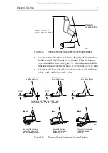
Page 14: ...or other parts extending from the hull that may cause turbulence or air bubbles The bracket has a quick release mechanism shown Figure 1 2 This allows the transducer to flip up if it hits any debris...

Page 15: ...Transom Mount Transducer Vertical Position D4872 2 Transducer in released position Allow a clearance of at least 254 mm 10 in No No No Average transom angle no wedge necessary Vertical transom place w...

Page 16: ...eeding Fin keel sailboats Mount to the side of the centerline and for ward of the fin keel 1 2 ft 300 600 mm Fullkeelsailboats Locateamidshipsandawayfromthe keelat the point of minimum deadrise angle...

Page 17: ...r Thru Hull Transducer 1 3 Aft Load waterline length LWL Pressure waves 6 12 in 150 300 mm Displacement hull Planning hulls Outboard and I O Inboard Step hull Fin keel sailboat Full keel sailboat D485...

Page 18: ...ducer The transducer cable may be extended up to a maximum of 60 ft 20 m using optional extension cables Thetransducercableconnectorhasanutthathasbeenremovedtoaid installation Toallow you tocomplete t...

Page 19: ...he 30 ft 10 m cable is not long enough extension cables are available from your Raymarine dealer See Table 1 2 on page 6 Total cable length from the transducer to the fishfinder must not exceed 60 ft...

Page 20: ...14 Transducers for Fishfinders All manuals and user guides at all guides com...

Page 21: ...Mount Transducer Preparation Transducer Mounting Bracket When installed the lower surface of the transducer should tilt down toward the rear at a slight angle 2 to 5 The mounting bracket includes a we...

Page 22: ...each location about 1 16 1 5 mm deep Drill pilot holes 3 4 19 mm deep using a 9 64 3 6 mm drill bit Topreventdrillingtoodeeply wrapmaskingtapearoundthedrill bitabout7 8 22mm from the tip Drillinonly...

Page 23: ...0 mm Cylinder wax tape and casting epoxy Fairing required with E66020 E66029 and E66043 transducers optional for E66024 E66033 and E66035 Level and protractor installation with a fairing Band saw or h...

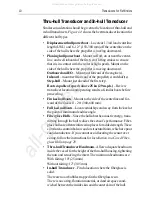
Page 24: ...cers See the table that follows The fairing is used to Vertically orient the sound beam by mounting the transducer par allel to the water surface Minimize aerated water flowing over the transducer s f...

Page 25: ...ransducer Fairing E66023 Cutting the Fairing 1 Measure the deadrise angle of the hull at the selected location using a digital level or bubble level and protractor see Figure 2 3 2 Tilt the band saw t...

Page 26: ...for installation on the star board side of the boat WARNING Always wear safety goggles and a dust mask when drilling 4 Recheck steps 1 through 3 then cut the fairing 5 Shape the fairing to the hull a...

Page 27: ...intthefollowing surfaces Exposed area of the housing including the acoustic window Bore of the housing up to 1 30 mm Outside wall below lower O ring Exposed end of the paddle wheel insert Paddle wheel...

Page 28: ...ing tape to the outside of the hull over the incorrect hole and fill it with epoxy 2 Cut a hole from outside the hull Fiberglass or wood hull Use a 2 51 mm hole saw Aluminium or steel hull Use a 2 1 8...

Page 29: ...s in the fairing Note The transducer must be flush with the fairing If it is recessed more than 1 64 0 5mm inside the fairing you may carefully file or sand the fairing flush with the transducer WARNI...

Page 30: ...file and sandpaper Figure 2 8 Using a Fairing and Backing Block Seating 1 Remove the transducer from the fairing if used 2 Stainless steel transducer in metal hull Slide the appropriate size isolation...

Page 31: ...mountinghole usingatwistingmotiontosqueezeoutexcessseal ant 3 From inside the hull slide the backing block onto the transducer cable and stem seating it firmly against the hull Figure 2 9 CAUTION Be...

Page 32: ...smooth water flow over the transducer s sensor be sure that the external surface of the installed triangular plug is FLUSH with the external curved surface of the fairing 9 Being sure the valve assem...

Page 33: ...nd the stem of the housing and twist it together with the long end Lead the wire straightupandthroughoneeyeinthecapnut thenthroughoneof the safety rings Loop the wire through the pull ring and twist i...

Page 34: ...Valve Assembly Notches Top view of paddlewheel insert Paddlewheel insert Housing and valve assembly Pull ring O rings Cable Key 2 Valve assembly Cap nut Housing BOW Flat side of paddlewheel blade fac...

Page 35: ...hrough the outer skin only 3 Usingthe23 8 60mm holesaw cutthroughtheinnerskinand most of the core from inside the hull The core material can be very soft Apply only light pressure to the hole saw afte...

Page 36: ...eral days 1 When the boat is placed in the water immediately check around the thru hull transducer for leaks Note that very small leaks may not be readily observed Do not to leave the boat in the wate...

Page 37: ...ed fiberglass hull installation Drill Hole saw for hull interior 4 100 mm Miniature disk sander Casting epoxy polyproxy 7035 7040 or resin Paper cup Stirrer Testing the Selected Mounting Location Esta...

Page 38: ...ow 1 Thismethodisrecommendedifthesensorwillbelocatednearthe stern and the boat has a minimum deadrise angle i Clean away any large build up of dirt and or grease using detergent or a weak solvent such...

Page 39: ...eline Lookforastabledepthreadingthatissimilartothebaseline compare the thickness and intensity of the bottom trace If the performance is close to the baseline this is a good mounting location Remember...

Page 40: ...d area and the underside of the base 4 Using a carpenter s square draw a line on the hull perpendicular to the keel through the center of the mounting location This will be used as a guideline to orie...

Page 41: ...to form a liquid tight seal and allow the adhesive to cure Figure 2 15 Aligning the Base Flange with 4 12 Deadrise Angle 7 Slide the transducer housing into the locking ring Turn the hous ing until th...

Page 42: ...he base 10 Lock the transducer assembly into the base by inserting the keys on the locking ring in the notches in the base Press down and rotate clockwise until seated see Figure 2 16 11 Route the cab...

Page 43: ...bjective is to bond the sensortotheinsidesurfaceofthehull souterskinwhilepreventing any moisture from penetrating the core CAUTION There isnoway to determine if the outerskinis solid notrapped air bub...

Page 44: ...g epoxy stirring carefully to avoid trapping air in the mix ture Pour this around the housing until the cavity is full Allow the casting epoxy to set for at least 1 hour Figure 2 18 Installation in a...

Page 45: ...ccept the connector with the nut removed approximately 13 16 or 21mm Before attaching the transducer cable you will need to attach the connector nut and split ring These items plus a wedge tool are in...

Page 46: ...ave installed Combined depth speed temp transducers have a 7 pin female connector Attach the transducer cable connector directly to the fishfinder Combined speed temperature transducers have a 3 pin f...

Page 47: ...Do not cut the transducer cable or remove the connector Do not try to shorten or splice the cable If the cable is cut it cannot be repaired Cutting the cable will also void the warranty All manuals a...

Page 48: ...42 Transducers for Fishfinders All manuals and user guides at all guides com...

Page 49: ...ay become jammed by dirt grit or barnacles Work this out of the mechanism then clean the unit with soap and water or alcohol Cleaning the Hull Use caution when sanding or cleaning the outside of the h...

Page 50: ...Common Problems and Their Solutions Table 3 1 Common Transducer Problems Problem Correction Fishfinder display freezes Check the transducer cable for damage If dam aged the cable and transducer must b...

Page 51: ...phrases If the answer you are seeking is not available click the Ask Raymarinetabto submityour ownquestiontoourtechnicalsupport staff who reply to you by e mail In the US Accessories and Parts Many R...

Page 52: ...requirements and can offer timesaving help in getting the equipment back into normal operation In the event that repairs can not be obtained conveniently product service may also be obtained by return...

Page 53: ...rtowww raymarine comandclick on the Customer Support link From there select Find Answers and click the Ask Raymarine tab Accessories and Parts Raymarine accessory items and parts are available through...

Page 54: ...48 Transducers for Fishfinders All manuals and user guides at all guides com...
Page 55: ...EMC Guidelines 6 In hull Transducer 31 Location 5 Thru hull Transducer 17 Transom Mount Transducer 15 L Location In hull Transducer 10 Transducer 6 M Maintenance 43 P Problem Solving 44 S Safety and S...

Page 56: ...50 Transducers for Fishfinders All manuals and user guides at all guides com a l l g u i d e s c o m...

Reviews: