5.1 Camera mounting
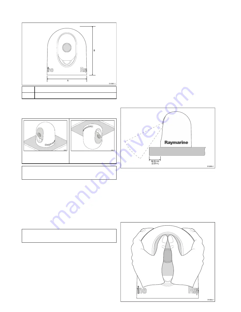
Product dimensions
A
B
D12851-1
A
151.56 mm (6 in.)
B
176.7 mm (7 in.)
Camera orientation
The camera can be mounted in 2 orientations referred to as
“Ball up” and “Ball down”.
D12852-1
Ball up: The camera is mounted on
top of the mounting surface.
D12853-1
Ball down: The camera is
suspended upside down, below the
mounting surface.
Note:
For ball down mounting you must invert the image
orientation using the Web interface or the camera’s On-Screen
Display menu.
Inverting the video orientation
When mounting in the Ball down configuration the image
orientation must be changed to invert the image. If required, the
image orientation should be changed prior to installation.
The web interface can be used to invert the video orientation.
1. Select
Setup
from the web interface.
2. Scroll down to
Image Orientation
.
3. Click the drop down box and select Invert.
The video image is now inverted.
4. Select
Save Settings
.
Note:
The video image orientation can also be inverted using
the On-Screen Display menu:
Menu > System Setup >
Enable / Disable Ball-Down Installation
Location requirement
When planning the installation location, consider the following
points:
• The camera is waterproof, and appropriate for above decks
mounting.
• The underside (inside) of the compartment or deck on to
which the camera is mounted must be weather-tight. You
must ensure protection from water ingress to cables and
connections.
• The mounting surface must be horizontal.
• If you cannot access both sides of the mounting surface, then
you will need to mount the camera “top down”.
• Fixings are supplied for a mounting surface of up to 41 mm
(1.6 in) thick. A thicker surface will require the installer to
provide alternative fixings.
• The camera mounting surface must be at least as large as
the footprint of the camera itself to ensure an adequate seal
with the O-ring.
• The camera should be mounted as high as practical,
but without interfering with any radar, navigational or
communications electronics.
• Choose a location that will provide the most unobstructed
view in all directions.
• Choose a location as close to the vessel’s center line as
possible. This provides a symmetrical view when looking
forward or aft.
• Select a location for the camera that is at least 7 cm (2.75 in.)
from any magnetic compass.
• Select a location that is at least 1 m (3 ft) from devices that
may cause interference, such as motors, generators and radio
transmitters / receivers.
• If installing an optional JCU, select a location for the JCU that
is at least 11 cm (4.33 in.) from any magnetic compass.
Distance to surface front edge
56.55 mm
(2.23 in.)
D12854-1
The unit should be mounted a maximum distance of 56.55 mm
(2.23 in.) from the front edge of the mounting surface to allow
for the full range of tilt.
Clearance above the camera
Ensure sufficient clearance is available above the unit to enable
removal of the outer cover.
The unit should only be installed in a location that has a
clearance of at least double the height of the unit.
Removing the outer cover
Follow the steps below to remove the camera’s outer cover.
D12855-1
T200


