


G-Series Reference Manual
108
DSM and transducer setup
Nearby vessels equipped with a fishfinder, or certain physical con-
ditions (like hard seabeds), can affect the DSM. Its setup menus
enable you to change settings to allow for this.
The system automatically adjusts the following settings to optimize
the fishfinder image.
•
Operating frequency.
•
Gain modes (Gain, Color Gain, TVG).
•
Power setting.
Note: The setup options available depend upon the DSM fitted
to your vessel.
Fishfinder settings should not ordinarily require adjustment.
Configure preset frequencies
Change the settings for one or more of the fishfinder presets. The
settings available depend upon the transducer fitted.
Target depth ID
Depth readings for identified targets.
Depth lines
Horizontal lines indicating depth.
White line and bottom fill
Distinguish between echoes from fish near the bottom and from the
bottom itself. (See illustration.)
Color Palette
Choose the color palette to suit your conditions or personal
preference.
75.9
ft
100
75
200 kHz: Auto
Gain: Auto High
75.9
ft
100
75
200 kHz: Auto
Gain: Auto High
75.9
ft
200 kHz: Auto
Gain: Auto High
75.9
ft
75
200 kHz: Auto
Gain: Auto High
D6833-3
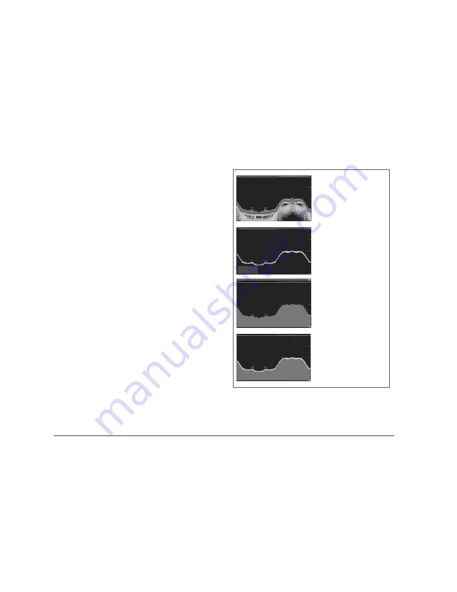
Standard fishfinder image
The standard fishfinder image displays the
bottom as a combination of features (mud,
sand, fish targets etc) with various sonar
signal strengths.
White line
When this feature is applied, a white lIne
is drawn along the bottom (as defined by
the digital depth value) and the detail
below the bottom removed.
Fish near the bottom can now be seen
more easily.
Bottom fill
When this feature is applied, the detail
below the bottom is removed and
replaced by a single contrasting color.
The bottom is now clearly defined and the
fish near the bottom can be seen more
easily.
White line and bottom fill
When both White Line and Bottom Fill
are applied, the bottom is defined by a white
line and the detail below it replaced by a
single contrasting color.
Both the bottom and fish near the bottom
are now clearly defined.
Summary of Contents for GPM400
Page 1: ...G Series Systems Reference Guide...
Page 2: ......
Page 3: ...G Series System Reference Guide Document Number 81276 1 Date June 2007...
Page 8: ...G Series Installation Commissioning 8...
Page 12: ...G Series Reference Manual 12...
Page 20: ...G Series Reference Manual 20...
Page 34: ...G Series Reference Manual 34...
Page 89: ...89 Chapter 7 Autopilot Integration...
Page 90: ...G Series Reference Manual 90...
Page 110: ...G Series Reference Manual 110...


