


77
Chapter 6: 3D Chart
The 3D chart view includes the same cartographic objects and nav-
igation features, like waypoints, as the standard chart. To move
around the 3D chart, and to display your chosen area at the
required scale, use pan and zoom as normal.
In the 3D chart, you can also adjust
rotate
and
pitch
settings.
•
Rotate rotates the view between 0° and 359°.
•
Pitch adjusts the vertical angle of view between 1° and 90°.
6.5
Operation modes
You can choose to view the chart in one of two modes:
•
Active motion mode.
•
Planning mode.
Active motion mode
This is the default mode. The screen shows an aerial view of the
3D chart with a viewpoint from above your boat, slightly behind it
and looking forward. As your position changes, the chart view auto-
matically updates.
You can set different viewpoints: see
View options
on page 81.
Rotating or panning the chart puts it into planning mode.
Planning mode
If you move the view away from your current location, the system
enters planning mode. You can view areas from different angles,
bearings and ranges but your vessel is no longer kept on screen
automatically.
The same controls and functions are available in both modes.
To enter planning mode:
• Pan to the area of the chart that
you want to view or
• Turn the rotary control (except
if set to CENTRE and ADJUST
PITCH).
Planning mode is indicated in the status bar by brackets around the
mode: (FWD).
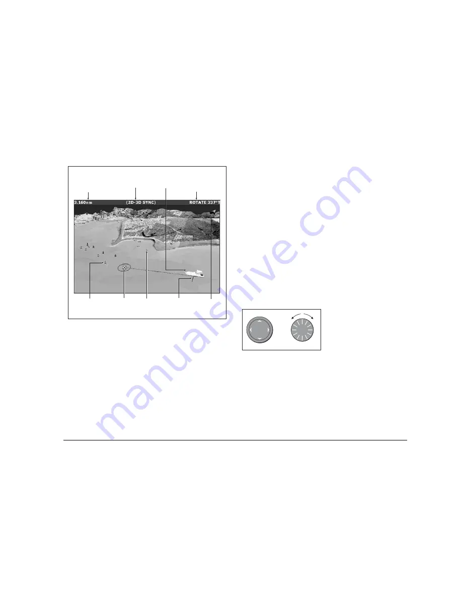
Mode
Shows mode
application is
working iin.
Rotation
Shows in degrees true,
how far the on-screen
view has been rotated
from your boat's heading
.
Range
Horizontal distance across
screen (halfway up the window
or at center of view). Shown in
selected system units.
Boat symbol
Boat's position on
chart. Select sail
or power boat.
Center-of-view
White cross indicates
center of chart view
at sea level.
North arrow
3D indication of True
North in relation to
the chart view.
Depth scale
Approximate
depth beneath
your boat.
Waypoint
With arrival
circle
Cartographic objects
Select objects for display
via the 3D Chart Setup
menu.
D8250_1
Or
D8737_1
Summary of Contents for GPM400
Page 1: ...G Series Systems Reference Guide...
Page 2: ......
Page 3: ...G Series System Reference Guide Document Number 81276 1 Date June 2007...
Page 8: ...G Series Installation Commissioning 8...
Page 12: ...G Series Reference Manual 12...
Page 20: ...G Series Reference Manual 20...
Page 34: ...G Series Reference Manual 34...
Page 89: ...89 Chapter 7 Autopilot Integration...
Page 90: ...G Series Reference Manual 90...
Page 110: ...G Series Reference Manual 110...


