83
Chapter 6: 3D Chart
6.9
Using the standard and 3D charts
together
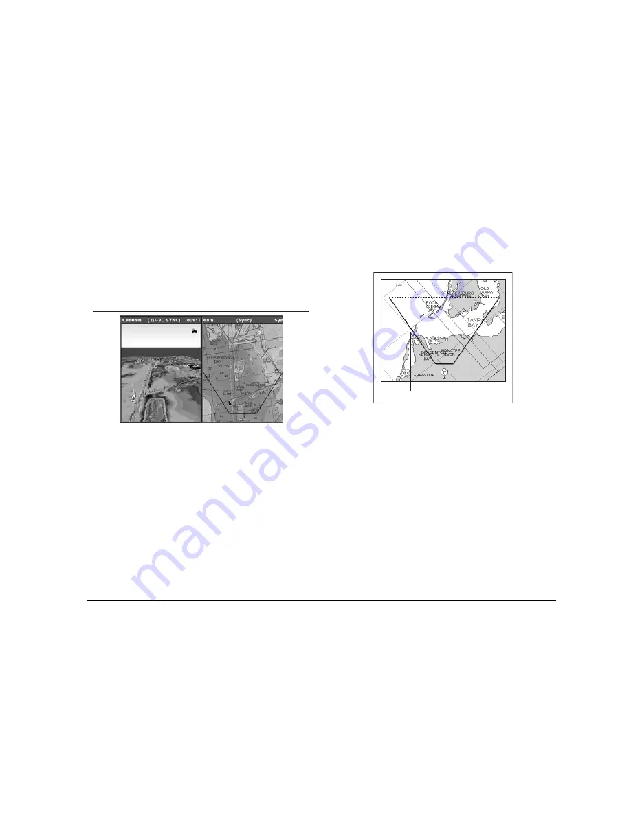
If the area in which you are navigating is unfamiliar, or visibility is
poor, working with standard and 3D chart windows side-by-side can
give you extra confidence and information. With the charts dis-
played side by side, a comprehensive view of the surrounding area
is available.
As with all multiple page sets, the active window is indicated by a
red border. To make changes to an application it must be in the
active window.
For information about setting up a page set to view two applications
together, see
page 25
.
3D view locator
The view locator is a polygon displayed on the standard chart which
outlines the boundaries of the area shown on the 3D chart. It is
shown as a blue line extending from the virtual eye point icon.
As you rotate, adjust pitch, pan or zoom the 3D chart view, the loca-
tor updates on the standard chart.
To display the 3D view locator
1. Make a standard (two-dimensional) chart window active.
2. Press the
PRESENTATION
softkey.
3. Press the
CHART LAYERS
softkey.
4. Toggle the
3D LOCATOR
setting to
ON
.
5. Press
OK
.
Chart synchronization
Chart synchronization enables you to synchronize heading, range
and position information on the standard and 3D charts.
When chart synchronization is
ON
:
•
2D/3D synchronization is flagged in the status bars.
D8255_1
D8256_1
View locator Eye point icon
Summary of Contents for GPM400
Page 1: ...G Series Systems Reference Guide...
Page 2: ......
Page 3: ...G Series System Reference Guide Document Number 81276 1 Date June 2007...
Page 8: ...G Series Installation Commissioning 8...
Page 12: ...G Series Reference Manual 12...
Page 20: ...G Series Reference Manual 20...
Page 34: ...G Series Reference Manual 34...
Page 89: ...89 Chapter 7 Autopilot Integration...
Page 90: ...G Series Reference Manual 90...
Page 110: ...G Series Reference Manual 110...