97
Chapter 8: The Fishfinder
Adjusting the position of the zoomed area
When the zoom function is selected, the system automatically
selects the zoom position so that the bottom details are always in
the lower half of the display. If required you can reposition the por-
tion of the image to be zoomed so that an alternative area is
displayed.
To set the zoom position
1. Press the
ZOOM
softkey.
2. Select
MAN
with the
ZOOM POSITION
softkey.
3. Reposition the zoomed image using the rotary controller.
4. Press
OK
.
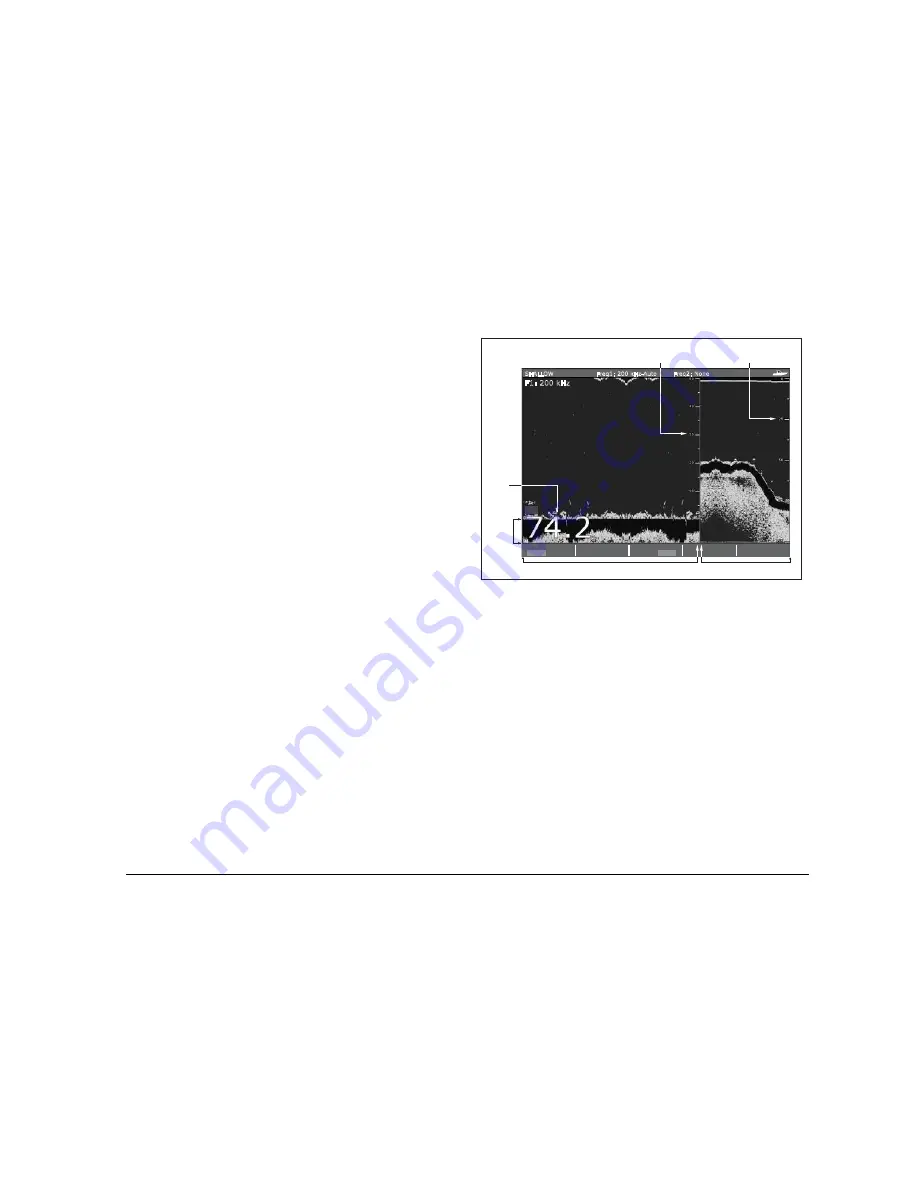
Bottom lock and bottom shift
The Bottom Lock function applies a filter to flatten the image of the
seabed and make any objects on or just above it easier to discern.
This feature is particularly useful for finding fish that feed close to
the bottom.
Bottom Lock is selected for individual fishfinder windows and can
replace or appear alongside the standard fishfinder image.
Adjusting the range of the bottom lock image allows you to view
more bottom details. You can also reposition the image on screen
to anywhere between the bottom of the window (0%) and the mid-
dle of the window (50%) by using the Bottom Shift control.
To adjust bottom lock
1. Toggle to
FULL
or
SPLIT
.
2. Use the appropriate softkeys and rotary controller to set the
range and bottom-shift values.
Using A-Scope to view a live image
The standard fishfinder display shows a historical record of fish-
finder echoes. If required, you can display a live image of the
bottom structure and the fish directly below the transducer by using
the A-Scope feature. The width of the bottom area covered by the
A-Scope is indicated by the number at the bottom of the window.
The A-SCOPE softkey
When A-Scope is on you can select one of three display modes:
BL
B-LOCK RANGE
50ft
BOTTOM SHIFT
14%
BOTTOM LOCK
FULL SPLIT
F1: 200 kHz
SHALLOW
Freq1: 200 kHz-Auto
Freq2: None
SELECT OPTION
BOTTOM LOCK
ADJUST
FREQ1 FREQ2
Depth from the surface
Bottom lock range
(distance from bottom)
Bottom
shift
Depth
reading
Bottom lock image
Standard fishfinder image
D10412-1
Summary of Contents for GPM400
Page 1: ...G Series Systems Reference Guide...
Page 2: ......
Page 3: ...G Series System Reference Guide Document Number 81276 1 Date June 2007...
Page 8: ...G Series Installation Commissioning 8...
Page 12: ...G Series Reference Manual 12...
Page 20: ...G Series Reference Manual 20...
Page 34: ...G Series Reference Manual 34...
Page 89: ...89 Chapter 7 Autopilot Integration...
Page 90: ...G Series Reference Manual 90...
Page 110: ...G Series Reference Manual 110...


