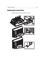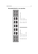
Inter-unit connections
109
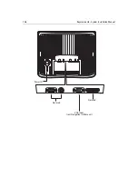
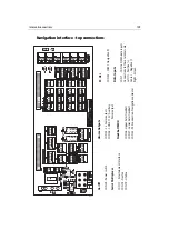
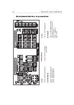
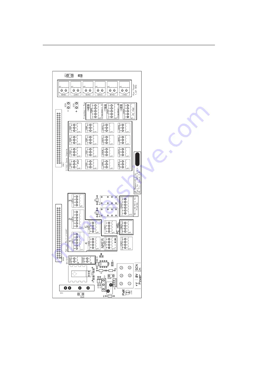
Navigation interface - top connections
On/Off
CON 29 - P
ower switch
Serial Multiple
xer
CON 17 - Entertainment Interface
CON 18 - Navtex
CON 19 - Lifeline
PC HSL
CON 23 - COM 1 Navigation PC
Data Inputs
CON 1 - CON 16 NMEA data inputs
Connections to these terminals are:
Left (1) - P
ositive (+)
Center - Negative (-)
Right - Screen
Alarm Outputs
CON 28 - 2 x
Alarm outputs
CON 36 - CON 41 12
V
Auxillary
P
ower output
Tr
ackball MUX
CON 26 - Upper helm trackball
CON 27 - Lower helm trackball
CON 33 - PS2 connection,
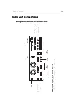
Navigation computer
D7535_1
Summary of Contents for H6
Page 1: ...System Installation Manual Document number 87035_1 Date November 2004 D7579_1...
Page 6: ...4 Raymarine H6 System Istalation Manual...
Page 16: ...10 Raymarine H6 System Installation Manual...
Page 17: ...11 This page should be replaced with the A3 sheet System Schematic...
Page 18: ...12 Raymarine H6 Installation Manual...
Page 26: ...20 Raymarine H6 System Installation Manual...
Page 27: ...21 This page should be replaced with the A3 sheets Cables...
Page 28: ...22 Raymarine H6 Installation Manual...
Page 48: ...42 Raymarine H6 System Installation Manual...
Page 62: ...56 Raymarine H6 System Installation Manual...
Page 72: ...66 Raymarine H6 System Installation Manual...
Page 98: ...92 Raymarine H6 System Installation Manual No Check Confirmed...
Page 103: ...Raymarine H6 Connection diagrams Raymarine 2004...
Page 104: ...98 Raymarine H6 System Installation Manual...
Page 110: ...104 Raymarine H6 System Installation Manual...
Page 121: ...115 This page should be replaced with the A3 sheet VGA Connections...
Page 122: ...116 Raymarine H6 Installation Manual...
Page 123: ...Installation templates D7579_1...

