


Planning the installation
17
•
Ventilation
- There must be sufficient space to allow an airflow around the units
to provide adequate ventilation. This airflow should be of a forced type if necessary.
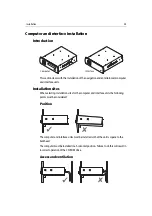
Display units
When planning the installation of the display units, the following should be considered
to ensure safe, comfortable and reliable operation:
•
Convenience
- The mounting location should be easily accessible to allow
operation of the front panel controls and should enable easy viewing of the display.
•
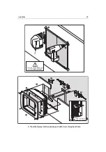
Access
- There must be sufficient space behind the displays to allow cable
connections to the rear panel connectors, avoiding tight bends in the cables.
•
Interference
- The selected locations for display units should be far enough away
from devices that may cause interference, such as motors, generators and radio
transmitter/receivers (see EMC guidelines in Important Information).
•
Environment
- Do not restrict airflow at the rear of the display units and sensor
modules; ensure there is adequate ventilation and protect units from physical
damage and excessive vibration. It is good practice to mount system components
in protected areas away from prolonged and direct exposure to rain and salt spray.
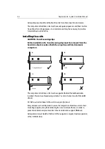
•
Ventilation
- To prevent any dimming of the displays by the in-built active
thermal management, it will be necessary to provide adequate ventilation.
Wherever possible this should be ambient cabin or fresh air. If the units are to be
installed in a binnacle (on a flybridge) or other enclosed space consideration should
be given to mechanical ventilation to ensure sufficient airflow.
Lifeline
When planning the installation of the Lifeline receiver, the following should be
considered to ensure safe, comfortable and reliable operation:
•
Lifeline receiver
- it is recommended that the Lifeline receiver is installed in a
suitable position as near horizontal as possible at the main helm.
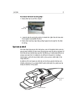
•
System antennas
- these should be positioned to give maximum coverage of the
boat. To achieve this it is necessary to mount one vertical and the other horizontal.
For example, on a flybridge cruiser, one could be installed in a horizontal position
in the radar arch, and one in a vertical position in either the engine room or a
forward cabin. On a sail boat, one could be installed in the sail locker and one in
the main accommodation.
•
Identification
- there can be up to eight Lifeline transmitter tags active at any
one time, each identified by a number. Consider the installation of a ‘white’ type
board near to the main helm for recording which crew member is assigned to
which tag.
Summary of Contents for H6
Page 1: ...System Installation Manual Document number 87035_1 Date November 2004 D7579_1...
Page 6: ...4 Raymarine H6 System Istalation Manual...
Page 16: ...10 Raymarine H6 System Installation Manual...
Page 17: ...11 This page should be replaced with the A3 sheet System Schematic...
Page 18: ...12 Raymarine H6 Installation Manual...
Page 26: ...20 Raymarine H6 System Installation Manual...
Page 27: ...21 This page should be replaced with the A3 sheets Cables...
Page 28: ...22 Raymarine H6 Installation Manual...
Page 48: ...42 Raymarine H6 System Installation Manual...
Page 62: ...56 Raymarine H6 System Installation Manual...
Page 72: ...66 Raymarine H6 System Installation Manual...
Page 98: ...92 Raymarine H6 System Installation Manual No Check Confirmed...
Page 103: ...Raymarine H6 Connection diagrams Raymarine 2004...
Page 104: ...98 Raymarine H6 System Installation Manual...
Page 110: ...104 Raymarine H6 System Installation Manual...
Page 121: ...115 This page should be replaced with the A3 sheet VGA Connections...
Page 122: ...116 Raymarine H6 Installation Manual...
Page 123: ...Installation templates D7579_1...


