28
Raymarine H6 - System Installation Manual
Display unit installation
Power requirements
CAUTION:
The display units are not intended for use on ‘positive’ ground boats. The
power input cable earth screen connections must be connected directly
to the boat’s ground.
The display units are designed to run on a DC power system rated at either 12 V or 24 V.
A 2.5 m length cable is supplied for connecting the display to the boat’s DC power
system.
The DC system should be either:
• Negative grounded, with the negative battery terminal connected to the boat’s
ground, or,
• Floating, with neither battery terminal connected to the boat’s ground.
Grounding the displays
It is important that an effective RF ground is connected to each display. The displays
must be grounded by connecting the drain wire (screen) of the power input cable to the
nearest ground point of the boat’s RF ground system.
Installation
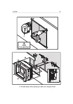
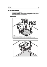
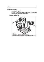
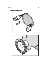
Each display should be installed as follows, using the templates supplied:
To install the display units:
1. Tape the templates into the required positions.
2. Using the template, drill a mounting hole 4.1 mm (0.16in) diameter in the 4 marked
positions for each template.
3. Cut the aperture in the surface, checking that there is nothing behind that the saw
might damage.
Summary of Contents for H6
Page 1: ...System Installation Manual Document number 87035_1 Date November 2004 D7579_1...
Page 6: ...4 Raymarine H6 System Istalation Manual...
Page 16: ...10 Raymarine H6 System Installation Manual...
Page 17: ...11 This page should be replaced with the A3 sheet System Schematic...
Page 18: ...12 Raymarine H6 Installation Manual...
Page 26: ...20 Raymarine H6 System Installation Manual...
Page 27: ...21 This page should be replaced with the A3 sheets Cables...
Page 28: ...22 Raymarine H6 Installation Manual...
Page 48: ...42 Raymarine H6 System Installation Manual...
Page 62: ...56 Raymarine H6 System Installation Manual...
Page 72: ...66 Raymarine H6 System Installation Manual...
Page 98: ...92 Raymarine H6 System Installation Manual No Check Confirmed...
Page 103: ...Raymarine H6 Connection diagrams Raymarine 2004...
Page 104: ...98 Raymarine H6 System Installation Manual...
Page 110: ...104 Raymarine H6 System Installation Manual...
Page 121: ...115 This page should be replaced with the A3 sheet VGA Connections...
Page 122: ...116 Raymarine H6 Installation Manual...
Page 123: ...Installation templates D7579_1...

