


Installation
29
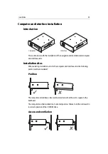
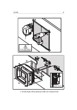
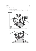
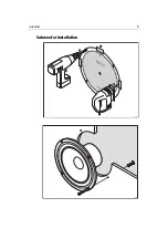
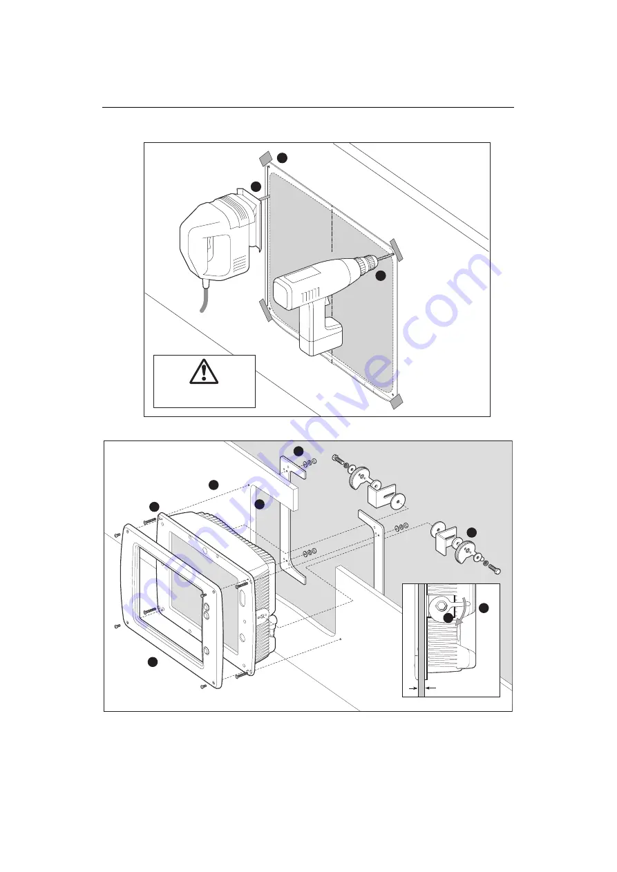
4. Place the display into the aperture, push a M4 screw through each hole.
15" LC
D P
anel tem
plate
Drill mou
nting ho
le
4.1 mm diameter
(4 positions)
Remove
shaded areas
only
302.2 mm (11.9 in)
391.6 mm (15.4 in)
center line
Instrument edg
e
Sun cover edge
D7410_-1
3
1
2
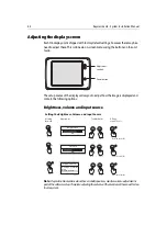
To ensure correct dimensions,
use the template provided.
-35.027˚
-35.027˚
-35.027˚
20.024˚
20.024˚
20.024˚
6 mm (0.24 in) min.
18 mm (0.71 in) max.
D7411_1
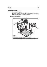
4
5
7
6
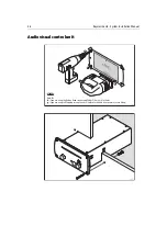
8
9
10
11
Summary of Contents for H6
Page 1: ...System Installation Manual Document number 87035_1 Date November 2004 D7579_1...
Page 6: ...4 Raymarine H6 System Istalation Manual...
Page 16: ...10 Raymarine H6 System Installation Manual...
Page 17: ...11 This page should be replaced with the A3 sheet System Schematic...
Page 18: ...12 Raymarine H6 Installation Manual...
Page 26: ...20 Raymarine H6 System Installation Manual...
Page 27: ...21 This page should be replaced with the A3 sheets Cables...
Page 28: ...22 Raymarine H6 Installation Manual...
Page 48: ...42 Raymarine H6 System Installation Manual...
Page 62: ...56 Raymarine H6 System Installation Manual...
Page 72: ...66 Raymarine H6 System Installation Manual...
Page 98: ...92 Raymarine H6 System Installation Manual No Check Confirmed...
Page 103: ...Raymarine H6 Connection diagrams Raymarine 2004...
Page 104: ...98 Raymarine H6 System Installation Manual...
Page 110: ...104 Raymarine H6 System Installation Manual...
Page 121: ...115 This page should be replaced with the A3 sheet VGA Connections...
Page 122: ...116 Raymarine H6 Installation Manual...
Page 123: ...Installation templates D7579_1...


