background image

3.4 Mounting

Transducer assembly

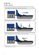
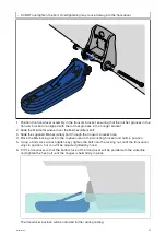
Follow the steps below to assemble the transducer ready for attaching to the Transom bracket.
1. Slide the hanger bracket over the top of the transducer until the notch in the side of the bracket

hanger aligns with the unlocked symbol on the side of the transducer.

2. Allow the hanger bracket to move down into the slots on the top of the transducer.

3. Slide the hanger bracket in the opposite direction from step 1, so that the notch in the side of the

bracket hanger aligns with the locked symbol on the side of the transducer.

4. Secure the hanger bracket to the transducer, using a 4 mm Hex wrench (Allen key) and the

supplied M5 hex bolt and washer.

24

Summary of Contents for HYPERVISION HV-100

Page 1: ...2019 Raymarine UK Limited 87362 3 Document number 09 2019 Date English en US Installation instructions HV 100 HYPERVISIONTM...

Page 2: ......

Page 3: ...r design patents pending Fair Use Statement You may print no more than three copies of this manual for your own use You may not make any further copies or distribute or use the manual in any other way...

Page 4: ......

Page 5: ...HV variants 14 2 4 Parts supplied 14 Chapter 3 Installation 17 3 1 Tools required 18 Anti fouling 18 3 2 Pre installation test 19 Testing the transducer 19 3 3 Selecting a location 20 Warnings and ca...

Page 6: ...ter 6 Maintenance 41 6 1 Routine checks 42 6 2 Transducer cleaning 42 6 3 Re applying anti fouling paint 42 Chapter 7 Technical support 43 7 1 Raymarine product support and servicing 44 7 2 Learning r...

Page 7: ...ove covers or attempt to access internal components unless specifically instructed in the documentation provided Warning Switch off power supply Ensure the vessel s power supply is switched OFF before...

Page 8: ...is product in accordance with the WEEE Directive The Waste Electrical and Electronic Equipment WEEE Directive requires the recycling of waste electrical and electronic equipment which contains materia...

Page 9: ...ot accept liability for any differences between the product and this document Please check the Raymarine website www raymarine com to ensure you have the most up to date version s of the documentation...

Page 10: ...10...

Page 11: ...product information Chapter contents 2 1 Product documentation on page 12 2 2 Applicable products on page 12 2 3 Required additional components on page 13 2 4 Parts supplied on page 14 Document and p...

Page 12: ...play 81388 Operation instructions For detailed operation instructions for your product refer to the documentation that accompanies your display All product documentation is available to download from...

Page 13: ...per 1 2 MHz DownVision Standard 350 kHz Conical high CHIRP 200 kHz 2 3 Required additional components This product forms part of a system of electronics and requires the following additional component...

Page 14: ...Element 7 HV E70534 Element 9 HV E70536 Element 12 HV 2 4 Parts supplied The following parts are supplied with your product Unpack your product carefully to prevent damage or loss of parts Check the...

Page 15: ...te used when routing cable through transom or a bulkhead 7 2 x adjustment slot washers 8 Transducer with 6 m 19 69 ft fitted cable 9 4 x escutcheon plate fixings 8x13 SUS316 10 3 x cable clips 11 3 x...

Page 16: ...16...

Page 17: ...Chapter 3 Installation Chapter contents 3 1 Tools required on page 18 3 2 Pre installation test on page 19 3 3 Selecting a location on page 20 3 4 Mounting on page 24 Installation 17...

Page 18: ...T use sealants containing acetate or silicone which can cause damage to plastic parts Anti fouling Where local regulations allow it is recommended that you coat your transducer using a water based ant...

Page 19: ...y 2 Fully submerge the transducer in water 3 Power up your HyperVision display The first time the display is powered up or after a factory reset has been performed the startup wizard is displayed Tran...

Page 20: ...ea where the least amount of turbulence and aeration occurs The transducer is NOT suitable for mounting on vessels where the transom is aft of the propeller s The transducer should be mounted as close...

Page 21: ...e mounted a minimum of 380 mm 15 in away from the propeller For clockwise rotating propellers mount the transducer on the starboard side for counter clockwise mount on the port side On a twin engine v...

Page 22: ...the effect such interference could have on the performance of your system Correct installation is required to ensure that EMC performance is not compromised Note In areas of extreme EMC interference...

Page 23: ...ve recommendations always ensure the maximum possible separation between different items of electrical equipment to provide the best conditions for EMC performance throughout the installation HV 100 p...

Page 24: ...with the unlocked symbol on the side of the transducer 2 Allow the hanger bracket to move down into the slots on the top of the transducer 3 Slide the hanger bracket in the opposite direction from st...

Page 25: ...ng section Important To help prevent chipping of fiberglass hulls use painter s tape to mask the drill hole areas behind the mounting template 1 Fix the supplied transducer mounting template to the se...

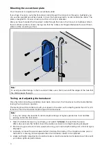
Page 26: ...w is not used until the transducer has been successfully tested Mounting the transducer assembly Important Only perform the installation with your vessel out of the water Do NOT lift or suspend the tr...

Page 27: ...llen bolt through the transom bracket hole 4 Place the M6 locking nut into the captive area on the mounting bracket and hold in position 5 Using a 5 mm Hex wrench Allen key tighten the bolt onto the l...

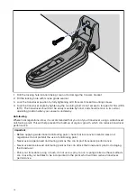
Page 28: ...es have been carried out the transducer must be tested before locking the transducer s position The testing should be carried out with your vessel in the water with a depth greater than 0 7 m 2 3 ft b...

Page 29: ...re re testing Important It may be necessary to make several adjustments to the transducer before obtaining optimum performance If the transducer requires repositioning ensure all old holes are filled...

Page 30: ...that you coat your transducer using a water based anti fouling paint This will help prevent the build up of organic growth which can reduce transducer performance Important Before applying water based...

Page 31: ...uld clean your transducer regularly and re apply anti fouling paint every 6 months or sooner depending on how rapidly organic growth builds up For guidance on transducer cleaning refer to p 42 Transdu...

Page 32: ...32...

Page 33: ...Chapter 4 Connections Chapter contents 4 1 General cabling guidance on page 34 4 2 Cable routing on page 34 4 3 Making connections on page 35 Connections 33...

Page 34: ...routing requirements for the transducer cable Important To avoid interference the cable must be routed as far away from VHF radio antenna devices and cables as possible Check that the cable is long en...

Page 35: ...hed off 2 Ensure that the device being connected to the unit has been installed in accordance with the installation instructions supplied with that device 3 Ensuring correct orientation push the cable...

Page 36: ...36...

Page 37: ...apter 5 System checks and troubleshooting Chapter contents 5 1 Operation instructions on page 38 5 2 Troubleshooting on page 38 5 3 Sonar troubleshooting on page 39 System checks and troubleshooting 3...

Page 38: ...common problems associated with installation and operation of your product Before packing and shipping all Raymarine products are subjected to comprehensive testing and quality assurance programs If...

Page 39: ...nt or broken missing If damage is detected replace the display or send it to an authorized service agent for repair Damaged transducer or cable 1 Check that the transducer cable connector is free from...

Page 40: ...ower cables as possible Poor problematic image Possible causes Possible solutions Poor and problematic images can be caused by the same issues as when no depth reading or bottom lock is possible In ad...

Page 41: ...Chapter 6 Maintenance Chapter contents 6 1 Routine checks on page 42 6 2 Transducer cleaning on page 42 6 3 Re applying anti fouling paint on page 42 Maintenance 41...

Page 42: ...formance Do NOT use harsh cleaning solvents such as acetone as this will damage the transducer Follow the guidance below to clean growth from your transducer use a soft cloth and a mild household clea...

Page 43: ...Chapter 7 Technical support Chapter contents 7 1 Raymarine product support and servicing on page 44 7 2 Learning resources on page 45 Technical support 43...

Page 44: ...Tel 44 0 1329 246 932 United States US E Mail rm usrepair flir com Tel 1 603 324 7900 Web support Please visit the Support area of the Raymarine website for Manuals and Documents http www raymarine c...

Page 45: ...al channel on YouTube YouTube LightHouse 3 tips and tricks Raymarine website Video Gallery Raymarine website Note Viewing the videos requires a device with an Internet connection Some videos are only...

Page 46: ...46...

Page 47: ...Chapter 8 Technical specification Chapter contents 8 1 Technical specification on page 48 Technical specification 47...

Page 48: ...ies to HyperVision products Sonar channels Conical high CHIRP sonar RealVision 3D Hyper RealVision 3D Standard SideVision Hyper SideVision Standard DownVision Hyper DownVision Standard Power 1 2 MHz H...

Page 49: ...Conformance specification Conformance EN 60945 2002 IEC 28846 1993 EMC Directive 2014 30 EU Australia and New Zealand C Tick Compliance Level 2 Technical specification 49...

Page 50: ...50...

Page 51: ...Chapter 9 Spares and accessories Chapter contents 9 1 Spares on page 52 9 2 Accessories on page 52 Spares and accessories 51...

Page 52: ...1 Spares Description Part number HV 100 Transom bracket R70651 9 2 Accessories Description Part number HV 100 trolling motor mount A80557 HyperVision transducer extension cable 4 m 13 12 ft A80562 52...

Page 53: ......

Page 54: ......

Page 55: ...00 transducer 12 HyperVision 48 I Installation Testing 19 28 Tools 18 L LightHouse 3 Tips and Tricks 45 LightHouse Sport Compatible displays 14 Location requirements General 20 M Maintenance 7 O Opera...

Page 56: ......

Page 57: ......

Page 58: ...FLIR Belgium BVBA Luxemburgstraat 2 2321 Meer Belgium Tel 44 0 1329 246 700 www raymarine com a brand by...

Reviews: