background image

Owner n

ot

es:

Summary of Contents for iTC-5

Page 1: ...iTC 5 Installation instructions ENGLISH Document number 87138 3 Date 03 2012...

Page 2: ......

Page 3: ...s patents pending or design patents pending Fair Use Statement You may print no more than three copies of this manual for your own use You may not make any further copies or distribute or use the manu...

Page 4: ......

Page 5: ...2 Converter connections 19 Chapter 4 Location and mounting 25 4 1 Unit dimensions 26 4 2 Mounting 26 4 3 Removing the front cover 28 Chapter 5 System checks and troubleshoot ing 29 5 1 Serial number...

Page 6: ...6 iTC 5...

Page 7: ...of a suitably rated fuse or automatic circuit breaker Caution Service and maintenance This product contains no user serviceable components Please refer all maintenance and repair to authorized Raymari...

Page 8: ...ling of waste electrical and electronic equipment Whilst the WEEE Directive does not apply to some Raymarine products we support its policy and ask you to be aware of how to dispose of this product Te...

Page 9: ...nstallation Chapter contents 2 1 About the iTC 5 Converter on page 10 2 2 Handbook information on page 11 2 3 System examples on page 11 2 4 Pack contents on page 15 2 5 Tools required on page 16 Plan...

Page 10: ...verter Instrument depth Instrument speed and sea temperature Raymarine Wind or rotavecta Rudder reference Fluxgate compass Note If there is a fishfinder in the system ensure that it does not operate a...

Page 11: ...dditional information included in the SeaTalkng reference manual In particular for assistance with constructing the SeaTalkng network and backbone connecting power and LEN loading calculations Descrip...

Page 12: ...2 x i70 Instrument displays 3 Terminated SeaTalkng T piece connector 4 Terminated iTC 5 5 Rudder reference transducer 6 Depth transducer 7 Fluxgate compass 8 Raymarine wind transducer or rotavecta 9 S...

Page 13: ...lkng system example 1 2 SMARTPILOT Status PWR Data STng VHF ANT AIS650 Class B Transceiver GPS ANT USB SeaTalk 12 V SeaTalkng 4 4 4 5 4 6 7 8 9 10 11 14 15 16 17 18 D12131 1 19 13 12 3 Planning the in...

Page 14: ...onnected via SPX 10 Multi Function display with built in GPS 11 SeaTalk to SeaTalkng converter 12 iTC 5 13 Terminated iTC 5 14 Trim tabs 15 Engine data connected via devicenet adaptor 16 Terminated Se...

Page 15: ...high current equipment will need to have a separate power connection SeaTalkng is a proprietary extension to NMEA 2000 and the proven CAN bus technology Compatible NMEA 2000 and SeaTalk SeaTalk2 devic...

Page 16: ...2 5 Tools required Tools required for installation 1 2 3 D12087 1 Item Description 1 Power Drill 2 Pozidrive screwdriver 3 3 2 mm 1 8 drill bit 16 iTC 5...

Page 17: ...Chapter 3 Cables and connections Chapter contents 3 1 General cabling guidance on page 18 3 2 Converter connections on page 19 Cables and connections 17...

Page 18: ...osed bulkhead or deckhead use a suitable watertight feed through Do NOT run cables near to engines or fluorescent lights Always route data cables as far away as possible from other equipment and cable...

Page 19: ...ate compass connection 4 Green Rudder reference transducer connection 5 Blue Depth transducer connection 6 SeaTalkng backbone connection 7 SeaTalkng spur connection 8 SeaTalkng backbone connection Sea...

Page 20: ...connector 4 Rotate locking collar clockwise 2 clicks until it snaps into the LOCKED position Transducer connections The iTC 5 allows connection of 5 transducers onto your SeaTalkng network Speed and s...

Page 21: ...name 1 Red Wind V 2 Screen Wind 0V shield 3 Green Sine wind direction 4 Blue Cosine wind direction 5 Yellow Anemometer signal Rotavecta connections 1 2 D12038 1 SPEED TEMP WIND COMPASS RUDDER DEPTH R...

Page 22: ...RUDDER DEPTH ROTA V ANE Item Cable color Signal name 1 Screen 0V shield 2 Blue Piezoceramic 3 Black Piezoceramic Warning iTC 5 High voltage Do not touch exposed transducer wires whilst the converter i...

Page 23: ...tention screw 9 Switch on the power supply Transducer cable lengths The table below shows the cable lengths supplied with transducers Transducer Cable length Speed and sea temperature 14 m Wind 30 m 5...

Page 24: ...24 iTC 5...

Page 25: ...Chapter 4 Location and mounting Chapter contents 4 1 Unit dimensions on page 26 4 2 Mounting on page 26 4 3 Removing the front cover on page 28 Location and mounting 25...

Page 26: ...rter ensure that you have Selected a suitable location where the converter is Reasonably well protected from physical damage maintained in a dry condition where there is no likelihood of the converter...

Page 27: ...unt the converter and slide down to secure in the mounting holes 7 Tighten the screws to lock the converter into position 8 Remove converter cover 9 Connect required transducer and SeaTalkng cables 10...

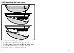
Page 28: ...t cover retaining screw 2 Push in the cover clip located on the right hand side 3 Pull the right hand side of the cover away from the unit slightly 4 Pull the left hand side of the cover away from the...

Page 29: ...on page 30 5 2 Typical system checks on page 30 5 3 iTC 5 LED Status indicators on page 31 5 4 System data troubleshooting on page 33 5 5 Raymarine customer support on page 34 5 6 Technical specifica...

Page 30: ...tus LED should be on Check transducers calibration settings Wind speed and sea temperature depth etc Ensure that instrument data is accurate and is available at all appropriate displays and instrument...

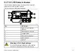
Page 31: ...ators D12133 1 ROTA V ANE 1 3 5 2 4 6 Item LED Indicator 1 Speed and sea temperature transducer 2 Wind transducer or rotavecta 3 Fluxgate compass 4 Rudder reference transducer 5 Depth transducer 6 Sea...

Page 32: ...ected Windvane anemometer Connected Wind speed pulse time out Lost valid signal windvane Not connected Rotavecta Connected Not connected Compass Connected Lost valid signal Not connected Rudder Connec...

Page 33: ...or engine interface Check the power to the SeaTalk bus Data source e g ST70 instrument or engine interface is not operating Refer to the manufacturer s handbook for the equipment in question Instrumen...

Page 34: ...Tel 44 0 13 2924 6777 Email ukproduct support raymarine com Product information If you need to request service please have the following information to hand Product name Product identity Serial number...

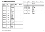
Page 35: ...4 Received PGN list NMEA2000 126996 Product information NMEA2000 126208 Acknowledge group function NMEA2000 126208 Command group function NMEA2000 126208 Request group function NMEA2000 127245 Rudder...

Page 36: ...36 iTC 5...

Page 37: ...Chapter 6 Options and accessories Chapter contents 6 1 Spares on page 38 6 2 SeaTalkng cables and accessories on page 38 Options and accessories 37...

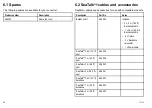
Page 38: ...ription Part No Notes Backbone Kit A25062 Includes 2 x 5 m 16 4 ft Backbone cable 1 x 20 m 65 6 ft Backbone cable 4 x T piece 2 x Backbone terminator 1 x Power cable SeaTalkng 0 4 m 1 3 ft spur A06038...

Page 39: ...001 Provides direct connection of a spur cable to the end of a backbone cable No T piece required SeaTalkng Blanking plug A06032 Description Part No Notes SeaTalk 3 pin to SeaTalkng adaptor cable 0 4...

Page 40: ...40 iTC 5...

Page 41: ...Owner notes...

Page 42: ...Owner notes...

Page 43: ......

Page 44: ...www raymarine com...

Reviews: