8.6 Dockside calibration
The dockside calibration process must be completed
before your SPX autopilot system can be used for
the first time. The Dockside wizard guides you
through the steps required for dockside calibration.
The Dockside wizard contains different steps
depending on whether you have a rudder reference
transducer fitted to your vessel:
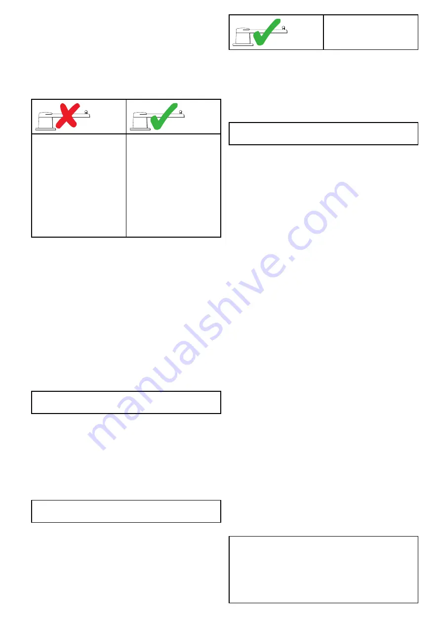
The following Dockside
wizard procedures only apply
to vessels
without
a rudder
reference transducer:
• Drive Type selection.
• Rudder Limit setting.
• Rudder Drive check.
The following Dockside
wizard procedures only apply
to vessels
with
a rudder
reference transducer:
• Drive Type selection.
• Align Rudder (rudder
alignment).
• Rudder Limit setting.
• Rudder Drive check.
On older SeaTalk SmartPilot systems the Dockside
wizard is named Dealer Settings. Please refer to
for calibration details.
Using the Dockside wizard
To access the dockside wizard follow the steps
below:
Ensure the pilot is in
Standby
.
1. Select
Menu
.
2. Select
Set-up
.
3. Select
Autopilot Calibration
.
4. Select
Commissioning
.
5. Select
Dockside Wizard
.
6. Follow the on-screen instructions.
Note:
You can cancel the Dockside wizard at any
time by pressing the
Standby
button.
Selecting a drive type
Drive Type selection is available when the pilot is in
standby, from either the Dockside wizard, or from the
Vessel setting menu:
MENU > Set-up > Autopilot
Calibration > Vessel Settings
.
With the
Drive Type
menu displayed:
1. Select your drive type.
Note:
If your drive type is not listed, contact your
Raymarine dealer for advice.
Checking the rudder alignment (Align
Rudder)
This procedure establishes port and starboard
rudder limits for systems using a rudder reference
transducer.
The rudder check forms part of the dockside
calibration process.
The following procedure only
applies to vessels with a
rudder reference transducer.
1. Center the rudder and select
OK
.
2. When prompted, turn the rudder hard to port and
select
OK
.
3. When prompted, turn the rudder hard to starboard
and select
OK
.
4. When prompted, turn the rudder back to the
center and select
OK
.
Note:
You can cancel Dockside calibration at any
time by selecting
STANDBY
.
Rudder Limit setting
As part of the Dockside calibration process, the
system will set-up the rudder limits.
•
For vessels with a rudder reference transducer
— This procedure establishes the rudder limit.
The rudder limit will be displayed with a message
confirming that the rudder limit has been updated.
This value can be changed if required.
•
For vessels without a rudder reference
transducer
— a default of 30 degrees is
displayed, and can be changed as required.
Checking the rudder drive
As part of the dockside calibration process, the
system will check the drive connection. Once it has
completed the check successfully, a message will
appear asking if it is safe for the system to take the
helm.
During this procedure the autopilot will move the
rudder. Ensure it is safe to proceed before pressing
OK.
When in dockside calibration mode, with the Motor
Check page displayed:
1. Centre and let go of the rudder.
2. Disengage any rudder drive clutch.
3. Select
CONTINUE
.
4. Check it is safe to proceed before selecting
OK
.
For vessels
with
a rudder reference transducer,
the autopilot will now automatically move the
rudder to port and then starboard.
5. For vessels
without
a rudder reference
transducer, you will be asked to confirm that the
rudder has turned to port by selecting
YES
or
NO
.
6. Select
OK
if it is safe to engage the rudder in the
opposite direction.
7. You will be asked to confirm the rudder turned to
starboard by selecting
YES
or
NO
.
8. Dockside calibration is now complete, select
CONTINUE
.
Note:
If you confirmed a “NO” response for the
rudder movement to both port and starboard, the
wizard will exit. It is possible that the steering
system did not move the rudder in any direction,
and it will be necessary to check the steering
system before completing the Dockside wizard
procedure again.
Commissioning - SPX and SmartPilot systems
53
Summary of Contents for P70
Page 2: ......
Page 4: ......
Page 10: ...10 p70 p70R ...
Page 14: ...14 p70 p70R ...
Page 28: ...28 p70 p70R ...
Page 29: ...Chapter 5 Installation Chapter contents 5 1 Mounting on page 30 Installation 29 ...
Page 38: ...38 p70 p70R ...
Page 48: ...48 p70 p70R ...
Page 58: ...58 p70 p70R ...
Page 68: ...68 p70 p70R ...
Page 74: ...74 p70 p70R ...
Page 80: ...80 p70 p70R ...
Page 94: ...94 p70 p70R ...
Page 110: ...110 p70 p70R ...
Page 118: ...118 p70 p70R ...
Page 121: ......


