15
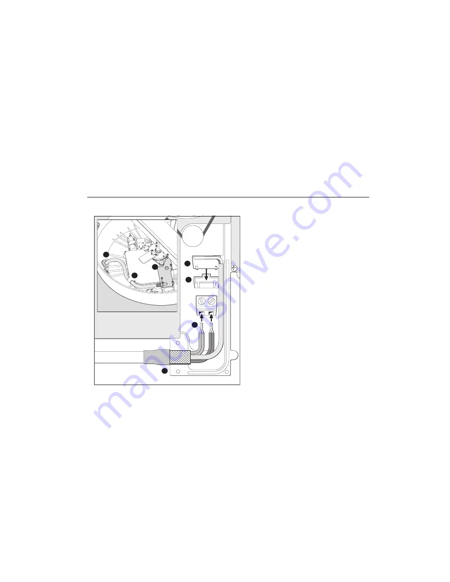
Connecting the inter-unit cable to the scanner
D8862_1
1
2
3
4
5
6
7
+ ve
- ve
CAUTION: Connections
Before starting to connect the inter-unit cable make
sure that the cable is not connected and power is not
applied to the display unit.
With the radome cover removed:
1. Remove the inner cover (1).
2. Slide the gland nut and grommet onto the inter-unit cable (2),
and insert the cable, still covered by its protective sleeve,
through the gland.
3. Carefully cut and remove the protective sleeve to expose the 8-
way plug (3) and the power cores (5).
4. Connect the red (+ve) and black (-ve) power cores (5). If you
have a 10m light or 15m inter-unit cable, connect both pairs of
cores to the relevant terminals.
5. Connect the 8-way plug (3) to the connector (4). The plug will
only fit one way.
6. Replace the inner cover (1), making sure that the exposed wire
braid (6) is secured in the cable clamp of the casting.
7. Clip the inter-unit cable into the strain relief (7).
8. Secure the nut on the watertight gland, making sure that it
grips the outer sheath of the cable.
9. Replace the radome cover - See “Completing the installation”
on page 16..


