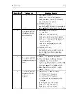
5-7
Maintenance
Item No.
Item No.
Item No.
Item No.
Item No.
Symptom
Symptom
Symptom
Symptom
Symptom
Possible Cause
Possible Cause
Possible Cause
Possible Cause
Possible Cause
3) B+ line: +13V
4) R5v line: +5V at Q33 output
5) COM8v line: +8v at IC12 output
6 DISC out at pin 4 of J2
b. Defective/device:
2nd IF IC (IC7), Disc (Z1), De-emph IC
(IC8), IC12-13, Q30, Q33-34, D19
4
a.Check CPU PCB as follows :
1) +5vA line
2) AF level: pin 3 of IC310
3) AF level: Q302 and Q303 output
4) AF level: cross-point SW at pins 7,
8, 17 of IC315
5) AF level: Buff amp at pin 1 of
IC319-321
b. Defective/device:
CPU (IC305), IC310, IC315, IC319-
321, Q302-304, Flex cable and
connector
5
a.Check +5V regulator of IC804
b. Check AF level on PCB as follows:
1) VR801 out pin 2 of J802
2) Analog SW out at pins 2, 6 of IC801
3) PA out at pin 1 of IC802, C817
c.Defective/devices: IC801 - 804,
VR801, C817
6
a.Check handset PCB as follows:
1) +9V line: IC714 output
2) +5V line: IC702 output
3) +2.5V Vref: Q703 output, VTH
output
4) AF leveL: pin 7 of IC704
5) AF level: pin 2 of IC711
6) AF level: pin 2 of IC706
No sound with AF
signal applied to
Main unit out
No sound with AF
signal applied to SP
box
No sound with AF
signal applied to
Handset
Summary of Contents for RAY230E
Page 1: ...RAY230 RAY230E Fixed Mount VHF Radio Owner s Handbook Document number R49006_1 Date May 2001...
Page 2: ......
Page 7: ...vii Declaration of Conformity goes here...
Page 102: ...3 80 Operations...
Page 138: ...6 16 Parts List and Drawings...
Page 150: ...7 12 Appendix...

