background image

IMO and SOLAS

The equipment described within this document is intended for
use on leisure marine boats and workboats not covered by
International Maritime Organization (IMO) and Safety of Life at
Sea (SOLAS) Carriage Regulations.

Technical accuracy

To the best of our knowledge, the information in this document
was correct at the time it was produced. However, Raymarine
cannot accept liability for any inaccuracies or omissions it
may contain. In addition, our policy of continuous product
improvement may change specifications without notice. As a
result, Raymarine cannot accept liability for any differences
between the product and this document. Please check the
Raymarine website (

www.raymarine.com

) to ensure you have

the most up-to-date version(s) of the documentation for your
product.

10

Ray260

Summary of Contents for Ray260

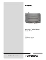
Page 1: ...Ray260 Installation and operation instructions English Date 1 1 2013 Document number 81343 3 EN 2013 Raymarine UK Limited 00 0 0 ...

Page 2: ......

Page 3: ...ts patents pending or design patents pending Fair Use Statement You may print no more than three copies of this manual for your own use You may not make any further copies or distribute or use the manual in any other way including without limitation exploiting the manual commercially or giving or selling copies to third parties Software updates Check the website www raymarine com for the latest so...

Page 4: ......

Page 5: ... 37 6 10 Adjusting the LCD backlight level 38 6 11 Adjusting the LCD contrast 38 6 12 Changing the transmit power 39 6 13 GPS setup 39 6 14 Handset station priority 40 Chapter 7 Digital selective calling DSC 41 7 1 Digital Selective Calling DSC 42 7 2 Distress calls 43 7 3 Urgency calls 45 7 4 Safety calls 46 7 5 Routine calls 46 7 6 Group calls 47 7 7 Position requests 48 7 8 Position tracking 48...

Page 6: ...Appendix B NMEA 2000 sentences 82 Appendix C VHF Channels 83 Appendix D Phonetic alphabet 90 Appendix E Prowords 91 6 Ray260 ...

Page 7: ...eived then repeat steps 2 to 4 above Safety notices Certified Installation Raymarine recommends certified installation by a Raymarine approved installer A certified installation qualifies for enhanced product warranty benefits Contact your Raymarine dealer for further details and refer to the separate warranty document packed with your product Warning Product installation and operation This produc...

Page 8: ...ence to radio communications However there is no guarantee that interference will not occur in a particular installation If this equipment does cause harmful interference to radio or television reception which can be determined by turning the equipment off and on the user is encouraged to try to correct the interference by one of the following measures 1 Reorient or relocate the receiving antenna ...

Page 9: ...ptimum EMC performance we recommend that wherever possible Raymarine equipment and cables connected to it are At least 1 m 3 ft from any equipment transmitting or cables carrying radio signals e g VHF radios cables and antennas In the case of SSB radios the distance should be increased to 7 ft 2 m More than 2 m 7 ft from the path of a radar beam A radar beam can normally be assumed to spread 20 de...

Page 10: ...his document was correct at the time it was produced However Raymarine cannot accept liability for any inaccuracies or omissions it may contain In addition our policy of continuous product improvement may change specifications without notice As a result Raymarine cannot accept liability for any differences between the product and this document Please check the Raymarine website www raymarine com t...

Page 11: ...Chapter 2 Document and product information Chapter contents 2 1 Handbook information on page 12 2 2 Product information on page 12 Document and product information 11 ...

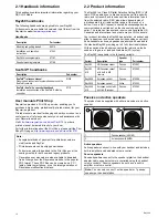
Page 12: ...displays 2 2 Product information The Ray260 is a Class D Digital Selective Calling DSC VHF radio DSC enables you to make a selective call to a specific radio and to transmit and receive position information to and from the selected radio DSC also allows transmission of a distress alert to all radios within range at the touch of a button Once a DSC request is sent and acknowledged voice communicati...

Page 13: ...pter contents 3 1 System integration on page 14 3 2 Typical systems on page 15 3 3 Installation checklist on page 16 3 4 Schematic diagram on page 16 3 5 System protocols on page 17 3 6 Parts supplied on page 17 Planning the installation 13 ...

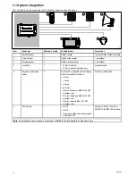
Page 14: ... Watt Loud hailer with listen back power data cable 5 Raymarine multifunction display 6 The Ray260 is compatible with the following Raymarine multifunction displays a Series c Series e Series gS Series C Series Widescreen NMEA 0183 DSC messages only E Series Widescreen NMEA 0183 DSC messages only G Series system NMEA 0183 DSC messages only SeaTalkng or NMEA 0183 6 GPS Receiver 1 RS130 RS125 Raymar...

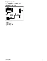
Page 15: ...andalone radio with peripherals or as part of a marine electronics network Standalone DSC VHF radio system 0 D12614 3 1 4 3 2 5 1 Ray260 base station 2 Handset 3 Handset extension cable 4 Handset adaptor cable 5 Passive speaker Planning the installation 15 ...

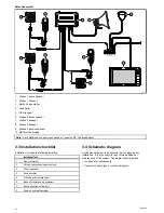
Page 16: ...llation checklist Installation includes the following activities Installation Task 1 Plan your system 2 Obtain all required equipment and tools 3 Site all equipment 4 Route all cables 5 Drill cable and mounting holes 6 Make all connections into equipment 7 Secure all equipment in place 8 Power on and test the system 3 4 Schematic diagram A schematic diagram is an essential part of planning any ins...

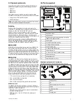
Page 17: ... equipment from many different manufacturers to be connected together and share information The NMEA 0183 standard carries similar information to SeaTalk However it has the important difference that one cable will only carry information in one direction For this reason NMEA 0183 is generally used to connect a data receiver and a transmitter together e g a compass sensor transmitting heading to a r...

Page 18: ...18 Ray260 ...

Page 19: ...s overview on page 20 4 3 Power connection on page 21 4 4 NMEA 0183 connection on page 22 4 5 Loud hailer connection on page 22 4 6 Handset connection on page 23 4 7 Passive speaker connection on page 23 4 8 Active speaker connection on page 24 4 9 SeaTalkng connection on page 24 Cables and connections 19 ...

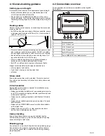
Page 20: ...er lines antennae Strain relief Ensure adequate strain relief is provided Protect connectors from strain and ensure they will not pull out under extreme sea conditions Circuit isolation Appropriate circuit isolation is required for installations using both AC and DC current Always use isolating transformers or a separate power inverter to run PC s processors displays and other sensitive electronic...

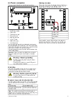
Page 21: ...gative wire on the power cable and does not require a drain shield to be connected to the base station s ground terminal Warning Positive ground systems Do not connect this unit to a system which has positive grounding Breakers fuses and circuit protection The power cable includes an in line fuse It is recommended that you fit an additional thermal breaker or fuse at the distribution panel In line...

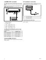
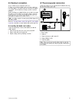
Page 22: ...cted to a compatible NMEA 0183 devices as shown in the table below Ray260 NMEA 0183 device Yellow Receive positive to Transmit positive Green Receive negative to Transmit negative White Transmit positive to Receive positive Brown Transmit negative to Receive negative Connecting NMEA 0183 wires NMEA 0183 wires should be connected securely and covered to prevent corrosion 4 5 Loud hailer connection ...

Page 23: ...4 7 Passive speaker connection and 4 8 Active speaker connection for details on connecting the handset and speakers Connecting handsets and cables Follow the steps below to connect handsets and extension cables together 1 Ensure the cable connectors are correctly orientated 2 Ensure connectors are fully inserted 3 Tighten locking collars by Rotating clockwise 4 7 Passive speaker connection A passi...

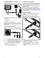
Page 24: ...ine multifunction displays using the SeaTalkng connector A Raymarine SeaTalkng GPS receiver cannot be connected directly to the Base station as GPS receivers are powered via the SeaTalkng backbone Note If your unit has both SeaTalkng and NMEA 0183 connected then you must select which connection you want to be active using the DSC Menu Connection Interface menu options Refer to 6 8 Selecting NMEA 0...

Page 25: ...ing Chapter contents 5 1 General location requirements on page 26 5 2 Base station dimensions on page 27 5 3 Base station mounting on page 28 5 4 Speaker mounting on page 28 5 5 Handset mounting on page 29 Location and mounting 25 ...

Page 26: ...on for your product ensure that the compass is not affected by the product when it is in a powered state Ventilation requirements To provide adequate airflow Ensure that equipment is mounted in a compartment of suitable size Ensure that ventilation holes are not obstructed Ensure adequate separation of equipment Mounting surface requirements Ensure units are adequately supported on a secure surfac...

Page 27: ... shown below 0 0 0 INTCM A D C B D12609 2 A 65 4 mm 2 57 in B 154 4 mm 6 07 in C 7 mm 0 275 in D 38 5 mm 1 5 in Speaker dimensions The dimensions of the Ray260 passive active speaker are shown below Note The passive speaker does not have a volume control knob 0 A G B C D E F D12607 1 A 112 mm 4 4 in B 112 mm 4 4 in C 20 3 mm 0 799 in D 15 55 mm 0 61 in E 25 mm 0 98 in F 30 mm 1 18 in G 91 5 mm 3 6...

Page 28: ...er follow the steps below D12608 1 0 The speaker is designed to be flush mounted 1 Check the selected location for the unit a clear flat area is required 2 Cut out the identified shaded area s from the mounting template 3 Fix the speaker mounting template supplied to the selected location using adhesive tape 4 Drill out the required mounting holes as indicated on the mounting template 5 If possibl...

Page 29: ...le size drill bit 4 Drill the center hole using a 25 mm 1 in hole cutting saw 5 Hold the clip in place and secure using the screws provided 6 Pull the connector end of the cable through the hole in the mounting panel Note The handset extension cable includes a speaker cable If you are not connecting an external passive speaker then cover the speaker cable with waterproof tape or sealant to prevent...

Page 30: ...30 Ray260 ...

Page 31: ...ew on page 34 6 6 Entering your MMSI number on page 35 6 7 Entering your ATIS ID on page 36 6 8 Selecting NMEA 0183 or SeaTalkng connection on page 37 6 9 Regional programming on page 37 6 10 Adjusting the LCD backlight level on page 38 6 11 Adjusting the LCD contrast on page 38 6 12 Changing the transmit power on page 39 6 13 GPS setup on page 39 6 14 Handset station priority on page 40 Getting s...

Page 32: ...he corresponding functions as identified by the on screen label 6 MENU DSC Press and release to access the radio menu Press and hold for 3 seconds to access the DSC menu 7 OK INTCM Press and release on menu options to confirm a selection or value Press and hold for 3 seconds to open the intercom menu 8 Channel Up and Down Moves the selected channel up or down Scrolls up or down through menu items ...

Page 33: ...nder or over recommended power An over voltage warning is displayed if the radio s supply voltage is between 15 7 V dc and 16 0 V dc The radio will automatically power down if the supply voltage exceeds 16 5 V dc the warning will be cancelled when the radios power supply voltage fails below 15 6 V dc An under voltage alarm is displayed if the radio s supply voltage is 10 5 V dc or less The radio w...

Page 34: ...u have assigned for each of the 3 soft button labels at the bottom of the screen This gives you a total of 9 favorite channels that you can switch to at the press of a button Telephone icon Indicates that the radio has received a voice mail Automatic channel changing blocked icon Indicates that your radio will not automatically switch to the channel requested by an incoming DSC call but will promp...

Page 35: ...NTACT DEALER is displayed on screen then you must contact your local Raymarine dealer and request them to input the MMSI number for you If ENTER MY MMSIis displayed then you can manually enter your MMSI The first character of the blank MMSI number will be highlighted Note If 0 is entered as the first digit then the second digit will automatically be changed to a 0 MMSI numbers beginning with 0 are...

Page 36: ...peat steps 2 to 9 above 11 If CONFIRMED is displayed then select Yes to confirm and register the ATIS ID The saved ATIS ID is displayed on screen e g ID 123456789 12 Select Back to go back to the ATIS Operation menu Note You can only enter the ATIS ID number once if you have stored an incorrect ATIS ID number in your product the product will have to be reset by an authorized Raymarine dealer Enabl...

Page 37: ...nal programming The frequency band of the product can be changed and must be set to the region the product will be used in The regions available are USA International Canada Changing the frequency band Before using the product to make DSC or other calls you must set the frequency band to the relevant region OK HI M AI N M ENU VHF OPERATIONv HAIL INTRCOM FOG GPS SETUP OK HI VHF OPERATI ON WATCH MOD...

Page 38: ... buttons to adjust the backlight to the required level 5 Select Ok to confirm the new backlight level 6 11 Adjusting the LCD contrast The LCD s contrast level can be adjusted by following the steps below 1 Press and release the MENU DSC button to display the main menu 2 Select SYSTEM CONFIG 3 Select CONTRAST The contrast level is displayed 4 Use the Channel Up and Channel Down buttons or the Left ...

Page 39: ...een entered manually If position data has been entered manually but has not been updated during the previous 4 hours the GPS icon flashes POS DATA OLD is displayed on screen and an audible warning is sounded This warning will be repeated every 4 hours until position is manually updated or GPS position data becomes available Where no position data is available or has not been manually updated for 2...

Page 40: ...s 2 and 3 are given the same priority with the first station in use given priority When a station is making a distress call that station is given priority until the distress call has been completed Station 1 can interrupt station 2 and 3 and take priority by pressing the PTT button When station 1 is in use stations 2 and 3 will display STATION 1 IN USE If station 2 or 3 is in use then station 1 wi...

Page 41: ...ge 45 7 4 Safety calls on page 46 7 5 Routine calls on page 46 7 6 Group calls on page 47 7 7 Position requests on page 48 7 8 Position tracking on page 48 7 9 Test calls on page 49 7 10 Voice mail on page 49 7 11 Received call logs on page 50 7 12 Phonebook on page 50 7 13 Group list on page 51 7 14 DSC options on page 51 Digital selective calling DSC 41 ...

Page 42: ... when there is danger to a vehicle or person that does not require immediate assistance When making an urgency call the following information is transmitted to all stations within range Vessel MMSI number Vessel position must be input manually if no GPS position data is available Local time must be input manually if no GPS position data is available Transmission frequency Once an urgency call is s...

Page 43: ...K NOW LEDGED FROM 0012345 67 ORIG mYSHIP 10 15 20 25 30 35 40 45 50 55 60 5 INTC M 1 Open the spring loaded door on the rear of the handset 2 Press and hold the DISTRESS button for 3 seconds Once the DISTRESS button is pressed a 3 second count down will begin when the count down reaches zero the distress call is transmitted 3 Wait for an acknowledgement of your distress call The distress call is r...

Page 44: ...e to channel 16 Muting a distress call You can ignore a distress call by muting the alarm and cancelling the distress call screen With an active distress call displayed 1 Press the Clear button to mute the alarm 2 Press the Clear button again to cancel the distress call screen The envelope icon will be turned off and normal operation is resumed Acknowledging a distress call Distress calls must onl...

Page 45: ...on that does not require immediate assistance Urgency calls are transmitted to all stations OK HI DSC M ENU INDIVIDUAL DISTRESS ALL SHIP OK HI ALL SHIP SAFETY URGENCY BACK BACK OK HI ALL SHIP URGENCY SELECT CHANNEL CH 0016 BACK SEND HI ALL SHIP URGENCY SELECT CHANNEL CH 0016 BACK SEND HI ALL SHIP URGENCY NOT DEFAULT CH CH 0072 HI ALL SHIP URGENCY CALLING HI ALL SHIP URGENCY TX COMPLETE CH CHG TO 0...

Page 46: ...ion pages 2 Select OK at any time to accept the safety call If auto channel change is turned on then the channel will automatically change after 10 seconds The radio is re tuned to channel 16 3 Listen on channel 16 for the safety message 7 5 Routine calls Individual calls can be made to ships and coast station contact saved in your phonebook or to any station by manually entering the stations MMSI...

Page 47: ...made to groups of vessels sharing the same Group MMSI numbers Routine group calls are made by selecting a group from the Group menu group calls are only received by stations sharing the selected group MMSI number Refer to the Group list section for details on adding groups to your radio Making a group routine call To make a routine call to a group of stations use the group menu OK HI DSC M ENU ALL...

Page 48: ...ically 3 If the position reply is set to manual then select SEND to send the position report 4 Select OK to resume normal operation 7 8 Position tracking The position tracking function enables regular position requests to be sent to selected target stations The position data will be available on a Raymarine multifunction display connected over NMEA 0183 or SeaTalkng Up to 3 phonebook contacts can ...

Page 49: ...lect OK to exit the test call and resume normal operation Receiving a test call Your radio will automatically acknowledge received test call from other stations When a test call is received a notification is displayed on screen to alert you that a test call has been received and automatically acknowledged 7 10 Voice mail The radio includes a voice mail feature The voice mail feature enables automa...

Page 50: ...SC menu 1 Select PHONEBOOK 2 Select NEW 3 To enter the MMSI number use the Channel Up and Channel Down buttons to select the number you want then select OK to confirm and move to the next digit When all 9 digits of the MMSI have been entered you can assign a name for the group 4 To enter a name for the contact use the Channel Up and Channel Down buttons to select the characters you want then selec...

Page 51: ...m and move to the next character 6 When you have completed your changes select OK to save the changes You are returned to your group list Deleting a group You can delete group MMSI details From the DSC menu 1 Select MY GROUP ID 2 Select the group you want to delete 3 Select DELETE 4 Select DELETE again to confirm and delete the group The group list is displayed and the group is now deleted 7 14 DS...

Page 52: ...52 Ray260 ...

Page 53: ...ority channels on page 55 8 4 Favorite channels on page 55 8 5 Sensitivity on page 56 8 6 Private channels on page 56 8 7 Automatic Transmitter Identification System ATIS and Marcom C mode on page 57 8 8 AIS on page 58 8 9 Voice recorder on page 58 8 10 System configuration on page 59 VHF operations 53 ...

Page 54: ... either ALL SCAN ALL SCAN 16 SAVED SCAN SAVED SCAN 16 Once selected the scan will start 3 You can exclude a channel from the current scan by selecting XCLUDE when the scan stops on that channel 4 You can stop the current scan at any time by selecting END Saving a channel You can add channels to the radio s memory so that they are included in the scan save and scan save 16 scan modes From the VHF o...

Page 55: ...ank that is displayed can be changed and channels can be added and removed as required The LCD displays which bank of favorites has been selected i e FAV 1 FAV 2 or FAV 3 Adding favorite channels Follow the steps below to add channels to the 3 favorite channel banks From the VHF operation menu Main menu VHF OPERATION 1 Select FAVORITE CH 2 Select either FAV CH BANK 1 FAV CH BANK 2 or FAV CH BANK 3...

Page 56: ...nt modes In local mode LOCAL is displayed on screen 3 Select BACK or press the Clear button to return to the previous menu 8 6 Private channels The radio may be able to receive additional private channels depending on the country it is used in and whether the appropriate licenses are held A list of private channel can be found in Appendix 1 Note Private channels are only available on the Ray260E a...

Page 57: ...le to disable ATIS operation Marcom C operation is set by the dealer at point of sale If you wish to enable or disable Marcom C mode you must contact your Raymarine dealer For further information please contact Raymarine technical support Enabling Disabling the ATIS function With the ATIS ID programmed you can now enable or disable the ATIS function as required by following the steps below Note If...

Page 58: ...ds long only the first 90 seconds is recorded Only 1 recording can be saved at a time when a new transmission is received any saved voice recording is automatically deleted Transmissions are not recorded when a scan mode or a watch mode is active Recording transmissions To enable automatic recording of transmissions the record function must be switched on From the main menu 1 Select VOICE RECORDER...

Page 59: ...IT Allows selecting of preferred speed units KNOTS MPH KPH FOG FREQ The frequency of the fog horn can be set 50 Hz to 850 Hz in 50 Hz increments LANGUAGE Allows selection of user interface language ENGLISH SPANISH FRENCH GERMAN ITALIAN SYSTEM TEST The System test function performs test to ensure equipment is connected and where applicable the radio is receiving appropriate data GPS Hailer Battery ...

Page 60: ...60 Ray260 ...

Page 61: ...Chapter 9 Hailer Fog horn and Intercom Chapter contents 9 1 Hailer on page 62 9 2 Fog horn on page 62 9 3 Handset intercom on page 63 Hailer Fog horn and Intercom 61 ...

Page 62: ...any vessel fishing but not trolling 1 long tone and 2 short tones RE STRICT TOW Restricted in ability to maneuver or towing another vessel 1 long tone and 2 short tones UNDER TOW This vessel is being towed 1 long tone and 3 short tones PILOT VESSEL This vessel is a pilot vessel 4 short tones AT ANCHOR Vessel is at anchor 12 consecutive rings AGROUND Vessel is aground 3 short rings 12 consecutive r...

Page 63: ...et Using the intercom From the main menu 1 Select HAILER FOG IC 2 Select INTERCOM A list of connected handsets is displayed 3 Select the handset you want to call 4 Wait for the handset station to acknowledge the call 5 Press and hold the PTT button and speak your message Responding to the intercom 1 Press the PTT button and acknowledge the call and to respond to subsequent voice messages Hailer Fo...

Page 64: ...64 Ray260 ...

Page 65: ...Chapter 10 Maintenance Chapter contents 10 1 Maintenance on page 66 10 2 Routine checks on page 66 10 3 Cleaning on page 67 10 4 Unit cleaning instructions on page 67 Maintenance 65 ...

Page 66: ...is waterproof keep the unit as dry as possible If you remove a handset connection ensure the dust cap is fitted to the connector 10 2 Routine checks The following periodic checks should be made Examine cables for signs of damage such as chafing cuts or nicks Check that the cable connectors are firmly attached and that their locking mechanisms are properly engaged Note Cable checks should be carrie...

Page 67: ...rasive or acid or ammonia based products Do NOT use a jet wash 10 4 Unit cleaning instructions The unit does not require regular cleaning However if you find it necessary to clean the unit please follow the steps below 1 Ensure power is switched off 2 Wipe unit clean with a damp cloth 3 If necessary use a mild detergent solution to remove grease marks Maintenance 67 ...

Page 68: ...68 Ray260 ...

Page 69: ...Chapter 11 Troubleshooting Chapter contents 11 1 Troubleshooting on page 70 11 2 VHF Radio troubleshooting on page 71 Troubleshooting 69 ...

Page 70: ...ior to packing and shipping subjected to comprehensive test and quality assurance programs However if you experience problems with the operation of your product this section will help you to diagnose and correct problems in order to restore normal operation If after referring to this section you are still having problems with your unit please contact Raymarine Technical Support for further advice ...

Page 71: ...t programmed Check MMSI number has been entered correctly DSC functions are not working Radio is set to ATIS mode Use of DSC is not permitted in ATIS regions You will be unable to make DSC distress and other types of digital selective call Position data is not shown Information not being received from GPS Check GPS is switched on and connected to the radio Check correct interface is selected NMEA ...

Page 72: ...72 Ray260 ...

Page 73: ...Chapter 12 Technical support Chapter contents 12 1 Raymarine customer support on page 74 Technical support 73 ...

Page 74: ...Raymarine Technical Support Department and details of worldwide Raymarine agents Telephone and e mail support In the USA Tel 1 603 324 7900 Toll Free 1 800 539 5539 E mail support raymarine com In the UK Europe and the Middle East Tel 44 0 13 2924 6777 E mail ukproduct support raymarine com In Southeast Asia and Australia Tel 61 0 29479 4800 E mail aus support raymarine com Product information If ...

Page 75: ...Chapter 13 Technical specification Chapter contents 13 1 Technical specification on page 76 Technical specification 75 ...

Page 76: ...enna impedance 50 Ohms typical Receiver Receiver type Double conversion super heterodyne Channels All available US International and Canadian VHF marine band Frequency range 156 025 MHz to 157 425 MHz 155 500 MHz to 163 275 MHz Private channels Sensitivity 12 dB SINAD Less than 0 35 µV Adjacent channel selectivity Better than 80 dB Spurious noise rejection Better than 80 dB Inter modulation reject...

Page 77: ...Chapter 14 Spares and accessories Chapter contents 14 1 Ray260 Spares Accessories on page 78 14 2 SeaTalkng cables and accessories on page 78 Spares and accessories 77 ...

Page 78: ... T70134 Includes 1 x 5 Way connector A06064 2 x Backbone terminator A06031 1 x 3 m 9 8 ft spur cable A06040 1 x Power cable A06049 SeaTalkng Backbone Kit A25062 Includes 2 x 5 m 16 4 ft Backbone cable A06036 1 x 20 m 65 6 ft Backbone cable A06037 4 x T piece A06028 2 x Backbone terminator A06031 1 x Power cable A06049 SeaTalkng 0 4 m 1 3 ft spur A06038 SeaTalkng 1 m 3 3 ft spur A06039 SeaTalkng 3 ...

Page 79: ...Talk to SeaTalkng spur 1 m 3 3 ft spur A22164 SeaTalk2 5 pin to SeaTalkng adaptor cable 0 4 m 1 3 ft A06048 DeviceNet adaptor cable Female A06045 Allows the connection of NMEA 2000 devices to a SeaTalkng system DeviceNet adaptor cable Male A06046 Allows the connection of NMEA 2000 devices to a SeaTalkng system DeviceNet adaptor cable Female to bare ends E05026 Allows the connection of NMEA 2000 de...

Page 80: ...80 Ray260 ...

Page 81: ...tion Receive Transmit Receive Transmit DSC Digital Selective Calling DSE Expanded Digital Selective Calling VDM AIS VHF Data Link Message GGA Global Positioning System Fix Data GLL Geographic Position Lat Long GNS GNSS Fix Data RMA Recommended Minimum Specific Loran C Data RMC Recommended Minimum Specific GNSS Data NMEA 0183 sentences 81 ...

Page 82: ...up Function 126464 PGN List 126996 Product Information 126026 COG SOG Rapid Update 126029 GNSS Position Data 129038 AIS Class A Position report 129039 AIS Class B Position Report 129040 AIS Class B Extended Position 129040 AIS SAR Aircraft Position Report 129040 Radio Frequency Mode Power 129808 DSC Call Information 129809 AIS Class B CS Static Data Report Part A 129810 AIS Class B CS Static Data ...

Page 83: ...ntain a listening watch on this channel 17 156 850 156 850 x State Control 18A 156 900 156 900 x Commercial 19A 156 950 156 950 x Commercial 20 157 000 161 600 Port operations duplex 20A 157 000 157 000 x Port operations 21A 157 050 157 050 x US Coast Guard only 22A 157 100 157 100 x Coast Guard Liaison and Maritime Safety Information Broadcasts Broadcasts announced on channel 16 23A 157 150 157 1...

Page 84: ...tation transmit side of an international semi duplex channel Operations are different from that of international operations on that channel 2 Channel 13 should be used to contact a ship when there is danger of collision All ships of length 20 metres or greater are required to guard VHF channel 13 in addition to VHF channel 16 when operating within US territorial waters 3 Channel 15 is receive only...

Page 85: ...hip ship shore commercial Towing on the Pacific coast 19A 156 950 156 950 All areas except PC Intership ship shore Canadian Coast Guard only 19A 156 950 156 950 PC Intership ship shore Various government departments 20 157 00 161 600 All areas Ship shore safety and ship movement Port operations limited to 1 watt maximum power 21A 157 050 157 050 All areas Intership and ship shore Canadian Coast Gu...

Page 86: ...d non commercial May be used to communicate with aircraft and helicopters in predominantly maritime support operations 73 156 675 156 675 EC Intership ship shore and commercial Commercial fishing only 73 156 675 156 675 All areas except EC Intership ship shore commercial non commercial and safety May also be used for communications with aircraft engaged in coordinated search and rescue and antipol...

Page 87: ...rrespondence Port operations and Ship movement 04 156 200 160 800 Public correspondence Port operations and Ship movement 05 156 250 160 850 Public correspondence Port operations and Ship movement 06 156 300 156 300 x Intership 07 156 350 160 950 Public correspondence Port operations and Ship movement 08 156 400 156 400 x Intership 09 156 450 156 450 x Intership Port operations and Ship movement 1...

Page 88: ...rations and Ship movement 86 157 325 161 925 Public correspondence Port operations and Ship movement 87 157 375 157 375 x Port operations and Ship movement 88 157 425 157 425 x Port operations and Ship movement Please be aware that Intership channels are for communications between ship stations Intership communications should be restricted to channels 6 8 72 and 77 If these are not available the o...

Page 89: ...850 Leisure F1 155 625 155 625 Fishing F2 155 775 155 775 Fishing Denmark Finland Norway Sweden F3 155 825 155 825 Fishing M1 157 850 157 850 Marina United Kingdom M2 161 425 161 425 Marina The national channels listed above have been allocated for the specific use within the countries listed To use these channels you must have the appropriate license WX Channels North America only Weather Channel...

Page 90: ...sounding or unfamiliar word radiotelephone users employ the international phonetic alphabet A ALPHA N NOVEMBER B BRAVO O OSCAR C CHARLIE P PAPA D DELTA Q QUEBEC E ECHO R ROMEO F FOXTROT S SIERRA G GOLF T TANGO H HOTEL U UNIFORM I INDIA V VICTOR J JULIET W WHISKEY K KILO X X RAY L LIMA Y YANKEE M MIKE Z ZULU 90 Ray260 ...

Page 91: ... An error has been made I SAY AGAIN I repeat e g important information I SPELL Phonetically spelling of the word OUT End of communication OVER I have completed this part of the message and am inviting you to reply RECEIVED Receipt acknowledgement SAY AGAIN Repeat your message STATION CALLING Used when a station is uncertain of the identity of a station which is calling Prowords 91 ...

Page 92: ...92 Ray260 ...

Page 93: ......

Page 94: ...www raymarine com ...

Reviews: