9
Chapter 2: Installation
2.2.3 Connection to External Navigation Equipments
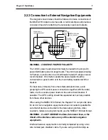
The diagram shown below should be followed to make connections of
the NMEA 0183 data to external units. A terminal strip would provide a
convenient means for attaching the necessary inputs and outputs.
WARNING:
OBSERVE PROPER POLARITY!
The 12VDC power leads should normally be routed to the ship’s DC
power distribution panel on larger boats. The unit draws approximately
0.25 amps, so connection to a circuit breaker rated at 5 amps or less is
recommended. On smaller vessels the power leads should be
connected to a panel switch or to the main battery isolation switch or
breaker.
For best noise immunity from other shipboard electronics, avoid
grouping the GPS sensor power connections together with the radar,
radio, or echo sounder power leads on the same circuit breaker, if
possible. The GPS’s wiring should be separated as much as possible
from these other devices.
When using the NMEA 0183 format, the Raystar 112 can provide data
for at 2 or more navigation equipments when connected in parallel. Be
sure that all devices connected to the data output ( plotters, video
sounders, radars) are programmed to use the NMEA 0183 data format.
WARNING:
Do NOT GROUND the Data, Data return lines, or the
Shield of the interface cable at any of the external navigation
equipments.
Interface between equipments is normally completed by using a two
wire, twisted pair, shielded, cable. If you are using a terminal strip as
Summary of Contents for Raystar 112
Page 2: ...GPS SENSOR OPERATION MANUAL...
Page 3: ......
Page 5: ...RAYSTAR 112 Installation and Operation Handbook...
Page 25: ...16 RAYSTAR112 InstallationandOperationHandbook...
Page 32: ......


