background image

60

RC435 and RC435i Chartplotters


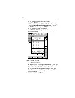
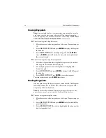
Figure 5-2: Route List Display

Displaying Route Leg and Waypoint Information

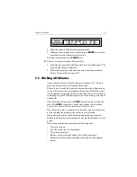
To display information about a route leg, move the cursor over the leg 
until its data is displayed in the status bar at the top of the screen 

To remove the data, move the cursor away from the route leg or press 

CLEAR

.

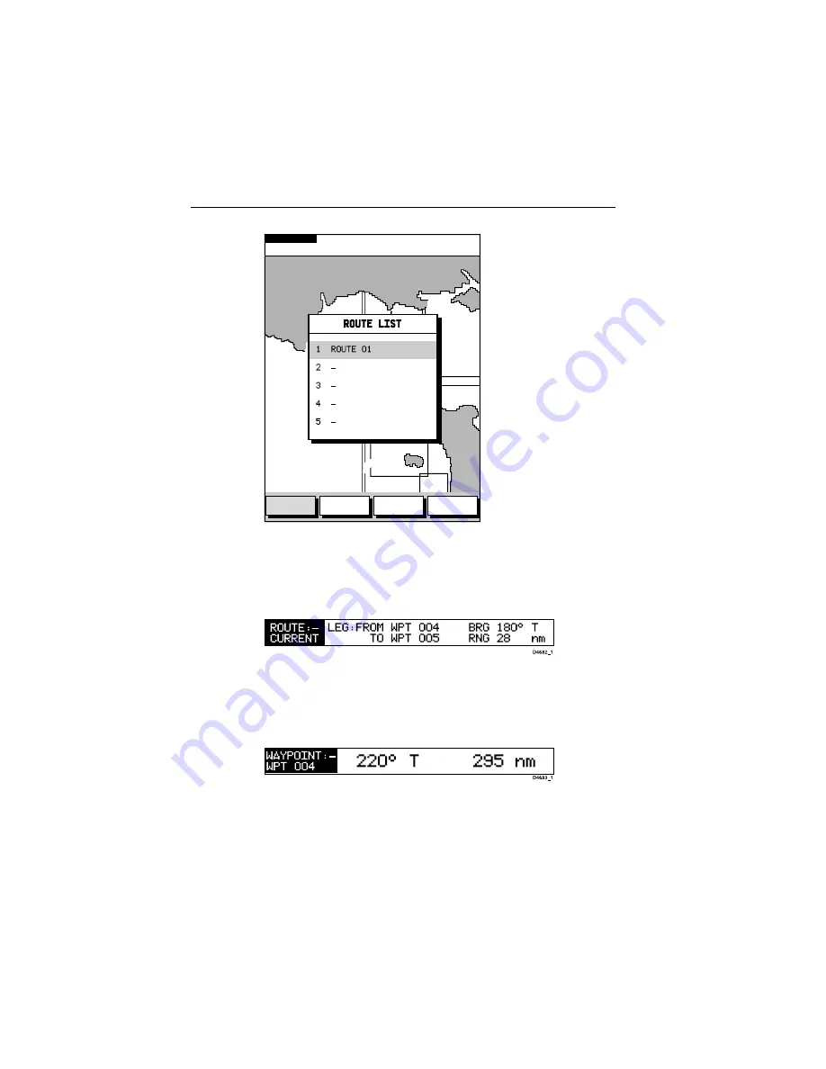
To display information about a route waypoint, move the cursor over the 
waypoint until its pop-up data box is displayed.


To remove the data, move the cursor away from the waypoint or press 

CLEAR

.

TOPSHAM

EXETER

TEIGNMOUTH

EXMOUTH

TORQUAY

DARTMOUTH

PLYMOUTH

ENPORT

SALCOMBE

PORTLAND

HARBOUR

ISLE O

CAP DE

LA HAGUE

ALDERNEY

GUERNSEY

JERSEY

PORTB

CSR 48°30.367'N
POS  1°35.636'W

128 nm

BRG    231°T
RNG  40.91nm

SIM OV NU

SHOW

ROUTE

ERASE
ROUTE

ROUTE

INFO

NAME

ROUTE

D6237_1

Summary of Contents for RC435

Page 1: ...RC435 RC435i Chartplotters Owner s Handbook Document Number 81236 2 Date August 2004 ...

Page 2: ...ii RC435 and RC435i Chartplotters ...

Page 3: ...eaterinstrument connected via the NMEA 0183 interface You can also download waypoints and routes to the RC435 435i from an external source Note This handbook contains important information about installing usingandmaintainingyournewRaymarineproduct Togetthebestfrom the product please read this handbook thoroughly Conventions Used Throughout this handbook dedicated buttons are referred to in bold c...

Page 4: ...ck of this handbook It is very importantthatyoucompletetheownerinformationandreturnthecardto the factory in order to receive full warranty benefits Technical Accuracy To the best of our knowledge the information in this handbook was correct as it went to press However our policy of continuous product improvement and updating may change specifications without prior notice As a result unavoidable di...

Page 5: ...nce with the instructions contained in this handbook Failure to do so could resultin poor product performance personal injury and or damage to your boat CAUTION Navigation Aid Although we have designed this product to be accurate and reliable manyfactorscanaffectitsperformance Asaresult itshouldonlybe used as an aid to navigation and should never replace common sense and navigational judgement Alw...

Page 6: ...ions you may have For information on Raymarine products and services contact either of the following United States Raymarine Inc 22 Cotton Road Unit D Nashua New Hampshire 03063 4219 USA Telephone 1 603 881 5200 1 800 539 5539 Fax 1 603 864 4756 Europe Raymarine Ltd Anchorage Park Portsmouth Hampshire PO3 5TD England Telephone 44 0 23 9269 3611 Fax 44 0 23 9269 4642 Or you may contact us on the Wo...

Page 7: ...stem 4 How it Works 5 Availability of WAAS and EGNOS Signals 6 Broadcast Continuation and Accuracy 6 Chapter 2 Installation 7 2 1 Introduction 7 EMC Installation Guidelines 7 2 2 Unpacking and Inspecting the Components 8 Items Missing 8 Optional Items 8 2 3 Installing the RC435 External GPS Antenna 9 Special Instructions for Installing the RC435i 9 Surface Mounting the External GPS Antenna 10 Pole...

Page 8: ... the Chart Scale 27 3 5 Using Navionics Gold Chart Cards 29 Inserting a Gold Chart Card 30 Removing a Gold Chart card 30 Loading the Chart Data 31 Displaying the Chart Data 32 Chapter 4 Setting Up 33 4 1 Introduction 33 4 2 System Set Up Parameters 33 Bearing Mode 35 Key Beep 35 Units 36 Variation 36 Variation Mode 36 Date Format 36 Time Offset 36 Language 36 Simulator 37 Simulated SOG 37 Simulate...

Page 9: ...oints 54 Moving Waypoints 54 5 3 Working with Routes 55 Creating a New Route 56 Saving the Current Route 58 Clearing the Current Route from the Screen 59 Retrieving a Route from the Database 59 Displaying Route Leg and Waypoint Information 60 Erasing or re Naming a Route 61 Route Info 61 Editing a Route 63 5 4 Following Routes and Going to Target Points 65 Follow a Route 66 Reverse a Route 66 Targ...

Page 10: ...or Deleting an Archived Track 90 Archiving a Waypoint Set 92 Loading or Deleting an Archived Waypoint Set 93 5 10 Displaying Chart Information 95 Port Services 95 Tide Information 97 5 11 Man Overboard MOB 103 5 12 Alarms 104 Chapter 6 Maintenance Troubleshooting 105 6 1 Maintenance 105 Routine Checks 105 Servicing and Safety 105 6 2 Resetting the System 106 6 3 Problem Solving 107 Troubleshooting...

Page 11: ...d Waypoint Lists Display Tide Heights Tide Currents Sun and Moon data Display vessel s position direction and track on screen Convert a track to a route SmartRoute Alarms and Timers Man OverBoard MOB to navigate back to a missing person or object Display and keys illuminated for night time use Operating Controls and Display Layout The chartplotter is operated by means of the following controls A m...

Page 12: ... Some items may also have options or settings If available thesearedisplayedinafunction baratthebottomofthescreen Note During many operations the cursor cannot be moved around the screen while a function bar is displayed for example and the cursor is used exclusively for selection In such cases three rapid beeps indicate invalid action FIND SHIP ROUTES WAYPOINTS MORE Chart card compartment Status ...

Page 13: ...t of your set up procedure see Chapter 4 Status Bar On the primary chart display the status bar at the top of the screen provides context sensitive information In general operation this will be the scale of the chart the position of the cursor lat and long and the rangeandbearingtothecursor Whenthecursorisplacedoveradynamic object the status bar will display information appropriate to that object ...

Page 14: ...and items selected for editing As with pop up menus when a database list is on screen a set of associated soft keys is also displayed use the trackpad to select an item from the list then use the appropriate function to edit the item For example a Waypoint or a Route can be erased 1 2 Satellite Differential System The RC435 435i GPS Antenna utilizes a satellite differential correction system to im...

Page 15: ...ce Stations are located at known positions and receive data continuously from GPS The Ground Reference Stations send their data to the Master Stations which calculate the error of the GPS received positions and generate correctional data The corrected differential signals are then sent to the two Geostationary Satellites which broadcast the corrected data on the standard GPS frequency making it av...

Page 16: ... is EGNOS compatible However at the time of going to print the EGNOS was still under test Further information on the WAAS and EGNOS systems can be found at www raymarine com Broadcast Continuation and Accuracy The continuation of the broadcast SD signals is not the responsibility of Raymarine Thenavigationalaccuracyofequipmentusingthesesatellite broadcast SD signals is not guaranteed ...

Page 17: ...ill perform under all conditions it is important to understand what factors could affect the operation of the product For optimum EMC performance it is recommended that wherever possible Raymarine equipment and cables connected to it are At least 3 ft 1 m from any equipment transmitting orcables carry ing radio signals for example VHF radios cables and antennas More than 7 ft 2 m from the path of ...

Page 18: ...d please contact your Raymarine dealer or our Product Support Department to obtain replacements Optional Items You may also order the following accessories from Raymarine Part Number Description E32040 E33019 RC435 Chartplotter with External GPS RC435i Chartplotter with Internal GPS E35009 External GPS Antenna for RC435 E32050 RC435 435i Sun Cover E35005 RC435 435i Mounting Bracket and Mounting Kn...

Page 19: ...enna can result in poor performance CAUTION GPS ANTENNA LOCATION When mounting the GPS Antenna flush to a deck surface avoid areas where the unit could be stepped on or tripped over Special Instructions for Installing the RC435i BecauseitsGPSantennais internal the RC435i shouldbemountedin an open location with a clear unobstructed view of the sky The RC435i should never be mounted below deck The R...

Page 20: ...PS Antenna above the mounting surface remove the two plastic tabs 1 obstructing the cable channel Note Failure to remove the plastic tabs from within the cable channel could result in cable damage 4 Screw the supplied brass studs 2 into the underside of the antenna 5 Attach the gasket 3 to the mounting surface ensuring that the holes match and pass the cable through the center hole or the cable ex...

Page 21: ... pole mount base A or insert the cable into the side exit channel B 3 Check that the cable is positioned correctly and secure the GPS Antenna to the pole mount base using the two screws provided If the cable is to exit from the side of the GPS Antenna through the side channel remove the two plastic tabs obstructing the cable chan nel Note Failure to remove the plastic tabs from within the cable ch...

Page 22: ...erference such as motors and generators Power Source The unit should be located near a DC power source Thepowercablesuppliedis1 5m 5ft butalongercablecanbeused if required Power must be supplied via a 1A quick blow fuse or cir cuit breaker Refer to Running the Cable on page 16 Interconnections The unit transmits navigation and waypoint data on NMEA and therefore can be connected to an NMEA compati...

Page 23: ... 2 2 RC435 RC435i Dimensions ANTENNA PWR NMEA 4 72in 120mm D6267 2 1 38in 35mm 1 38in 35mm 1 26in 32mm 5 08in 129mm 7 00in 178mm 2 52in 64mm 1 57in 39 9mm 5 12in 130mm plug clearance 7 48in 190mm 6 93in 176mm 5 28in 134mm 3 74in 95mm ...

Page 24: ... RC435 can be panel mounted using the panel mounting kit accessory available from your local Raymarine dealer A mounting template appears at the end of this handbook Note The RC435i with Internal GPS antenna cannot be panel flush mounted Panel mount the unit as follows 1 Check the selected location for the unit A clear flat area at least 185mm 7 in wide by 185mm 7 in high with at least 120mm 4 in ...

Page 25: ...es at the rear of the unit hand tight only 8 Place the gasket on the unit and slide the unit into the panel cut out 9 Secure the unit with the thumb nuts hand tight only Figure 2 3 Figure 2 3 RC435 Panel Mounting Arrangement 20 02 20 02 and 35 02 and 35 02 D6265 1 ...

Page 26: ...rovides power and RF connection to the associated GPS Antenna CAUTION Do not connect disconnect the GPS Antenna from the display unit while power is applied Such action could cause irreparable damage Connect the antenna using the attached cable as follows 1 If not already installed mount the GPS Antenna Section 2 3 2 Feed the cable through to the rear of the Chartplotter 3 Coilupany unusedcablein ...

Page 27: ... connected to the vessel s ground Floating with neither battery terminal connected to the vessel s ground A 1 5m 5ft power cable is supplied If a longer power cable run is required use the supplied power cable to connect to the unit plus a suitable connector block to connect to the extension cable The supplied power cable cores have a cross section of 2 0mm2 15 AWG Longerpowercablerunsmayrequirela...

Page 28: ...black wire to the terminal 3 Use a suitable junction box to connect to any NMEA equipment 4 Cut any unused wires short or insulate and tape back If the power connections are accidentally reversed the system will not function Use avoltmeter to check that the input power leads are connected with the correct polarity Pin Function Color 1 Battery positive 10 0VDC to 18 0VDC Red 2 Battery negative Blac...

Page 29: ...cables are secured and protected Initial Switch On To switch on the chartplotter press the POWER key If necessary adjust the lighting and contrast see Chapter 4 If desired change the default language settings as follows 1 Press the PAGE key to display the setup function bar 2 Usingtrackpadleft right selecttheSYSTEMSETUPfunctionandpress ENTER TheSYSTEMSETUPmenuisdisplayed listingtheparameters and t...

Page 30: ...rating correctly perform the following checks 1 Press the trackpad left right up down and check cursor movement and normal scrolling action 2 Insert a Navionics Gold Chart card for the area of your vessel You are asked to select one to use See Select Chart on page 42 3 Use the RANGE key to zoom in and check that the new chart car tridge data is displayed 4 Ensure that position data is available us...

Page 31: ...ystem you can adapt these procedures to suit your method of operation Simulator The Chartplotter includes a Simulator mode which allows you to practice operating your chartplotter without live GPS data Section 3 3 Simulator Mode describes how you can switch to this mode Simulator mode can be used in the following situations Beforethe chartplotterhasbeeninstalledonyourvessel Connectthe Chartplotter...

Page 32: ...have read and understood the warning press the ENTER key If this is the first time that the chartplotter has been switched on and no chart card is installed the display shows the background world map at Lat 0 Lon 0 Toturntheunitoff pressandholdthePOWERkey Acountdowntimeris displayed Keepholding thekeyuntilthisreaches zerowhentheunit will power off Changing the Lighting and Contrast You can change ...

Page 33: ...Simulator Mode When simulator mode is started your initial simulated position is wherever the cursor was last positioned To practice using the chartplotter in a particular chart area use the trackpad to pan to that area then switch simulator ON When in Simulator mode a flashing SIM indication is displayed in the top left hand corner of the chart screen Note If real position data is available and t...

Page 34: ...hange the display mode Move around the chart by panning the display changing the chart center and changing the chart scale Selecting the Display Mode UsethePAGEkeytoselectthedisplaymode Selectthefollowingmodes by repeat presses of the PAGE key as listed below and as shown overleaf Set Up functions see Chapter 4 Course Deviation Indicator CDI Bearing Distance Indication BDI Waypoint data Navigation...

Page 35: ... O CAP DE LA HAGUE ALDERNEY GUERNSEY JERSEY PORTB CSR 48 30 367 N POS 1 35 636 W 128 nm BRG 231 T RNG 40 91nm SIM OV NU TIME 02 18 DATE 10 07 04 STEER STARBOARD l ETA WAYPOINT 03 03 10 07 04 TTG WAYPOINT 00 44 ETA ROUTE 03 44 10 07 04 TTG ROUTE 01 25 5 0 4 6 3 4 9 N 0 0 1 1 0 4 1 1 W SUNRISE 05 05 SUNSET 21 14 TODAY AT POSITION VESSEL POSITION 50 46 338 N 1 10 391 W COG 313 T SOG 5 0 Kts WAYPOINT ...

Page 36: ...ere are three ways in which you can reposition the chart Use the trackpad to move the cursor to the edge of the chart the chart pansacross Thismethodisusefuliftheareayouwishtoseeisjustoff screen Automatically re center the vessel using the FIND SHIP function Change the chart scale using the RANGE key to zoom out and in to a newarea Thismethodis usefuliftheareayouwish toseeissomedis tance away Usin...

Page 37: ...hen no chart data is available for that scale To enable plotter mode see Chapter 4 Setting Up You can change the chart scale for two purposes To see either a smaller area in more detail or a larger area in less detail To move the display to another area of the chart by zooming out to a small scale chart then zooming in to another location Each time you press the RANGE key the chart scale changes t...

Page 38: ...etail is indicated by a box around the area 3 In normal operation the unit will allow you to zoom in as far as the chart detail allows By selecting PLOTTER MODE in CHART SETUP you can overzoom beyond that of the chart card and the vessel way points routes and tracklines will be displayed without cartography To zoom out to a less detailed chart press the top of the RANGE key as many times as desire...

Page 39: ... are availableonNavionicsGoldChartcards eachofwhichcanstoreupto20 charts in an electronic format A Gold Chart card provides an appropriate level of detail for a given geographic area and scale this data can be displayed down to a range of 1 8 nm on the screen height if the data is available To obtain Navionics Gold Chart cards contact your local dealer or visit www navionics com or www navionics i...

Page 40: ... 4 Gently press the card home If inserted correctly the card release but ton will move outwards as the card is inserted If this is not the case flip the card and retry 5 To prevent the ingress of water close the chart card door and press firmly until an audible click is heard Removing a Gold Chart card CAUTION DO NOT use a metallic instrument e g a screwdriver or pliers to aid removal as doing so ...

Page 41: ...rds Loading the Chart Data A Gold Chart Card can hold multiple chart area portfolios When the flash card is inserted for the first time and the display powered on the following is displayed To insert chart card To remove chart card D6235 1 Card release button Card release button ...

Page 42: ...fferent portfolio is desired this can be accessed by the SELECT CHART option see Select Chart on page 42 Displaying the Chart Data The new chart data will be displayed when you move the cursor into an area covered by the new chart The boundary of each chart is defined by a box or rectangle You can switchoffthechart boundariesdisplayaspart ofchartset up describedin Chapter 4 Setting Up LOAD CHART E...

Page 43: ...d default settings GPS status and default settings The set up parameters are selected via three soft keys System Set Up controlling overall functionality Chart Set Up controlling the chartplotter functions including way point information and vectors GPS Set Up displaying the GPS Antenna status Note The additional TRACK SET UP function is coveredin Chapter 5 Op eration This section provides instruc...

Page 44: ...aved until the ENTER key is pressed 6 Press CLEAR to clear the function bar and return to normal operation Note To return all settings to their original factory settings perform a factory reset as described in Chapter 6 The table below lists the System menus and their options shows the factory default settings and provides space to make a note of personal settings Each parameter is described in th...

Page 45: ... MAGnetic TRUE TRUE KEY BEEP OFF ON ON DISTANCE UNITS NAUTICAL MILES nm KILOMETERS km STATUTE MILES sm NAUTICAL MILES SPEED UNITS KNOTS KILOMETERS PER HOUR KPH MILES PER HOUR MPH KNOTS DEPTH UNITS METRES FEET FATHOMS METRES VARIATION 30 W to 30 E 1 steps 0 0 E VARIATION MODE MANUAL AUTO AUTO DATE FORMAT DD MM YY or MM DD YY DD MM YY TIME OFFSET UTC or local offset value up to 13 hours in 1 hour st...

Page 46: ...ff The Default value is zero Note Variation can only be changed if the VARIATION MODE is set to MANUAL Variation Mode This can be set to AUTO or MANUAL In AUTO mode the RC435 435i automatically calculates and sets the magnetic variation Set this to MANUAL to enter your own value Date Format Set the preferred date format DD MM YY or MM DD YY The selected setting is retained when the unit switched o...

Page 47: ...ated COG below If a GOTO or Follow is started the simulator does not use the selected value of COG but instead generates a value of COG that simulates the navigation function in progress When GOTO or Follow is stopped the user selected value of COG is used Simulated SOG Use horizontal movements of the trackpad to adjust the value of SOG which is adjustable in 1 knot intervals from 00 to 99 The Def...

Page 48: ...ing to your system configuration and your personal preferences To set the Chart default parameters 1 Press the PAGE key to display the SET UP function bar 2 Usethetrackpadleft righttohighlighttheCHARTSETUPfunctionand press ENTER to display the Chart Set Up menu Figure 4 2 Chart Set Up Menu D4694_1 ORIENTATION SPOT SOUNDINGS D6248 1 ...

Page 49: ...sandtheiroptions shows the factory default setting and provides a space to make a note of the new default setting Parameter Options Factory Default New Setting ORIENTATION NORTH UP COURSE UP HEAD UP NORTH UP PLOTTER MODE OFF ON ON SHOW WAYPOINTS OFF ON ON WAYPOINT SYMBOL FISH SKULL ANCHOR or X X AUTOZOOM OFF ON ON SCREEN AMPLIFIER OFF ON ON COG VECTOR OFF ON OFF ARRIVAL CIRCLE 0 01nm 0 05nm 0 1nm ...

Page 50: ...OG value is shown upwards To update the Course Up reference while Course Up is the current mode re select COURSE UP from the set up menu If a new course is selected a new target waypoint for example the chart displays the new course upwards Head Up The chart is displayed with the vessel s current COG upwards As the heading changes the chart rotates periodically to maintain orientation Note Head Up...

Page 51: ...eyondthelargestcartographicscale unless Plotter Mode is activated When in MOB mode Autozoom is selected automatically and will zoom in as far as possible irrespective of the selection of Plotter Mode Screen Amplifier Screen amplifier mode makes best use of the screen by positioning the vessel on the screen so as to increase forward visibility The screen amplifier is only active when the cursor is ...

Page 52: ... off The alarm is set to OFF on power up XTE Alarm The selected value is used as the cross track error limit The alarm is triggered when the cross track error exceeds the selected limit when a GOTO oraRouteFollowis in progressandanalarmmessageis displayed Select Chart Use SELECT CHART to access different charts from the same Gold Card Use the trackpad up down buttons to select the desired chart an...

Page 53: ...layed The selected setting is retained when the unit switched off Light Sectors When ON light sectors are displayed The selected setting is retained when the unit switched off Presentation Set to display navigation mark in either INTERNATIONAL or US symbology The selected setting is retained when the unit is switched off Position Calibration When ON all position data is offset from WGS 84 by the v...

Page 54: ...tion and the position entered Note Pressing ENTER with a selected offset of more than 2nm gives a warning message which is cleared on any key press The Calibration Set Up mode maintains and the user can either reselect an acceptable offset or press CLEAR to reset the value to zero and return to the Set Up menu 4 4 GPS Setup The GPS set up page provides information for the status of the tracked nav...

Page 55: ...angles are used in a triangulation process to calculate your position HDOP Horizontal Dilution Of Position is a measure of this accuracy a higher figure signifies greater error In ideal circumstances the figure should be in the region of 1 0 The Fix Status can indicate SD FIX where a Satellite Differential fix has been acquired FIX OK where a normal GPS fix has been acquired NO FIX where no satell...

Page 56: ...F Select ON to allow the unit to use SD corrections if available Select OFF to force the unit to calculate a normal GPS fix with no satellite GPS corrections 3 Press CLEAR twice to return to the normal display To reset SD GPS 1 Using the trackpad left right highlight RESET GPS in the function bar and press ENTER 2 Press CLEAR twice to return to the normal display D6253 2 SD GPS ENABLE RESET GPS ...

Page 57: ... cursor or at the vessel s position or at a specific lat long Waypoints can also be placed before the chartplotter is installed on your vessel When a new waypoint is placed it is displayed using either the default symbol of a cross or an alternative symbol available from the Chart Set Up menu as described in Chapter 4 The waypoint is added to the waypoint list and named with the next available num...

Page 58: ... to the way point list and named using the next available number The waypoint functions remain displayed so that further way points can be placed Use EDIT WAYPOINT to name the waypoint as described inEditing Waypoint Details on page 52 iii When finished placing waypoints press CLEAR 4 To place a waypoint at the vessel s position Select PLACE WPT AT VESSEL A new waypoint is placed at the ves sel s ...

Page 59: ...ng the Waypoint List Select WAYPOINT LIST The Waypoint List and associated function Soft Keys are displayed Figure 5 1 Waypoint List Display 7 Select MAKE NEW WAYPOINT Thewaypointisplacedatthecurrentvesselpositionor ifaGPSfixis not available the cursor position The new waypoint is added to the Waypoint List and named with the next available number The EDIT WAYPOINT function is now highlighted allo...

Page 60: ...ew waypoint and transfer waypoints To select a waypoint using the cursor 1 Movethecursoroverthewaypoint the WAYPOINT OPTIONS function bar together with help text is displayed 2 Press ENTER to select the waypoint function bar The selected waypoint can be edited via these functions To select a waypoint using the Waypoint List 1 Press ENTER to display the primary function bar 2 SelectWAYPOINTSandpres...

Page 61: ...topofthe screen or the waypoint details can be viewed on the waypoint list To display waypoint data Movethecursoroverthewaypoint Thewaypointdataisdisplayedinthe status bar indicating waypoint number name bearing and range from vessel dashes are shown if no fix is available While the cursor is over the waypoint the WAYPOINT OPTIONS function bar is displayed To remove the waypoint data Move the curs...

Page 62: ... Waypoint function bar is displayed 4 To edit the waypoint name select EDIT NAME The NAME WAYPOINT window is displayed 5 Use the trackpad to enter or edit the name as follows Use trackpad left right to move the cursor to the character to be changed Up to eight characters can be used Use trackpad up down to scroll through the characters When editing is complete press ENTER the waypoint name is upda...

Page 63: ...t characters 6 To edit the waypoint symbol select EDIT SYMBOL i Use trackpad left right to highlight the desired symbol ii Press ENTER toacceptthechoiceorCLEAR to aborttheoperation 7 To change the waypoint s position select EDIT POSITION The cursor is placed in the Position field in the Waypoint List i Use trackpad left right to select the latitude longitude fields ii Use trackpad up down to scrol...

Page 64: ...ist as previously described The waypoint list function bar is displayed 2 Use trackpad up down to move through the list to highlight the desired waypoint 3 SelectEDITWAYPOINTandpressENTERtodisplaytheEditWaypoint function bar 4 Select ERASE WAYPOINT Press ENTER to erase the waypoint To return to chart mode press CLEAR three times Moving Waypoints Any waypoint except the target waypoint can be moved...

Page 65: ...n be current and is displayed if it is in the field of view as solid lines connecting waypoints If following the route the current leg is shown as a dotted line After a route has been created the GOTO key can be used to follow the route The GOTO key provides various other options as described in Section 5 4 Following Routes and Going to Target Points Up to 20 routes can be saved in the route datab...

Page 66: ...t level functions 3 Select MORE to see more functions 4 Select MORE again to return to the first level functions 5 Press CLEAR twice to return to chart mode Creating a New Route Note If there is a current route on screen it is cleared when MAKE ROUTE is selected Ensure that this route is saved before continuing If following the current route you must STOP FOLLOW see page 72 before a new route can ...

Page 67: ...r to the next waypoint position a dotted line connects the cursor to the last placed waypoint 5 Press ENTER again The next waypoint is placed and the dotted line changes to a solid line Note If the waypoint was placed incorrectly it can be deleted by press ing CLEAR Successive waypoints can be deleted in this way 6 RepeatStep 4 and Step 5 until all waypoints have beenplaced Up to 50 waypoints can ...

Page 68: ... on the list is highlighted You can use track pad up down to select another position in the list which can be a blank slot or an existing route you no longer need 4 Press ENTER to save the route Press ENTER again in response to the prompt to name the route or CLEAR to save as the default ROUTE XX where XX is the next avail able number When naming a route use the trackpad to move the cursor right o...

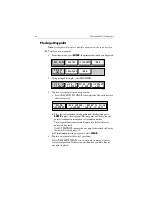
Page 69: ...t been saved a prompt gives the options ENTER to save or CLEAR to remove the route from the screen 4 To save the route in the database press ENTER The Name Route functions are displayed see Saving the Current Route on page 58 Retrieving a Route from the Database Aroutefromthedatabaselistcanbeselectedasthecurrentroute Thelist is accessed from the second set of ROUTES functions To select a route as ...

Page 70: ...om the route leg or press CLEAR To display information about a route waypoint move the cursor over the waypoint until its pop up data box is displayed To remove the data move the cursor away from the waypoint or press CLEAR TOPSHAM EXETER TEIGNMOUTH EXMOUTH TORQUAY DARTMOUTH PLYMOUTH ENPORT SALCOMBE PORTLAND HARBOUR ISLE O CAP DE LA HAGUE ALDERNEY GUERNSEY JERSEY PORTB CSR 48 30 367 N POS 1 35 636...

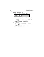
Page 71: ...ect ROUTES followed by MORE then ROUTE LIST The route list is displayed with the selected route highlighted 2 Select NAME ROUTE and press ENTER 3 To name or rename a route use trackpad left right to select each char acter to be edited Use trackpad up down to scroll through the charac ters 4 Press ENTER to accept the new name or CLEAR to cancel the opera tion 5 Press CLEAR three times to clear the ...

Page 72: ...n keys to scroll through the list 3 To display the ETA at each route waypoint selectTIME ETA andpress ENTER 4 To enter a planned SOG rather than actual SOG select PLANNED SOG and press ENTER Use the trackpad left right keys to change the planned SOG value and press ENTER to recalculate route with this value 5 To recalculate using actual SOG select ACTUAL SOG and press ENTER 6 Press CLEAR four time...

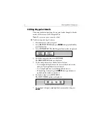
Page 73: ...ROUTES then EDIT ROUTE and press ENTER the PLACE WAY POINT function is displayed 2 Add waypoint s to the route by moving the cursor and pressing ENTER in the same way as the route was first created 3 Remove waypoints from a route by pressing CLEAR in the same way as the route was first created 4 When your changes are complete press the GOTO key to end route editing 5 Press CLEAR twice to return to...

Page 74: ... waypoint appears 5 Press CLEAR again to remove the function bar and route leg data The waypoints in the current route are re numbered to identify the new positions Note If you already have 50 waypoints in your route the system will not allow you to add any more and a warning message will be displayed To remove a waypoint from the route using the cursor 1 Place the cursor over the waypoint 2 Selec...

Page 75: ... This section explains how to perform the following tasks Follow a route Reverse a route Target Point Arrival Altering the route including joining at a selected waypoint advanc ing waypoints and restarting XTE Go to an individual point either an existing waypoint or the cursor Go to the nearest facility or a selected port Stop and Restart Follow Goto Analarmistriggeredwhenapproachingawaypoint Chap...

Page 76: ...e target waypoint This line remains fixed on screen as the vessel moves The function bar is removed Reverse a Route This option enables a return route to be generated from an existing route which is then followed in reverse order with waypoints renumbered accordingly To reverse the current route From the normal chart display 1 PressENTER to displaytheprimaryfunctionbar thenselectROUTES followed by...

Page 77: ... Press any key to cancel the arrival alarm The target becomes the origin the next waypoint becomes the target pointandthetwoareconnectedbyadottedlineindicatingthecurrentleg Ifthe targetwaypoint wasthesubjectofaGoTo orwasthe lastwaypoint in a route the pop up alarm is cleared Alter a Route A route can be followed from a selected waypoint Join a route or if already following advanced to the next way...

Page 78: ...E Restart XTE is useful if you find yourself off track and prefer to go directly to your target rather than get back onto the original track While following a route or going to a target point you can restart the XTE ThissetstheXTEtozeroandmovestheorigintothevessel sactual position CAUTION Care must be taken when restarting XTE that your new track does not take the vessel into a dangerous situation...

Page 79: ...ing waypoint a port or nearest facility or the current cursor position Go to a Waypoint To navigate directly to an existing waypoint 1 From the normal chart display i Use the trackpad to position the cursor over the desired waypoint until the waypoint options function is displayed then press ENTER to display the waypoint functions or ii Press the GOTO key to display the waypoint options and select...

Page 80: ...waypoint begins Go to Cursor Note If navigation is currently in progress or if the cursor is homed Find Ship it is not possible to go to cursor To navigate directly to the current cursor position 1 Press the GOTO key and select GOTO CURSOR The GOTO CURSOR function now has help text appended to it 2 Use the trackpad to position the cursor as desired 3 Press ENTER to start the GOTO or CLEAR to cance...

Page 81: ...to display the Port List 2 Use trackpad up down to select the desired port and press ENTER to start the GoTo or CLEAR to cancel the operation A dotted line is drawn between the current vessel position and the target waypointwhichisplacedattheport Thelineremainsfixedonthescreen as the vessel moves Bearing Range and Cross Track Error are calculated for the target waypoint in the same manner as for a...

Page 82: ...functions see Chapter 4 Course Deviation Indicator CDI Bearing Distance Indication BDI Waypoint data Navigation data Time Date data Return to Chart display Note PresstheGOTO keyinanydisplaymodetoreturntonormalChart display To change the display mode 1 PressthePAGEkeytoshowtheSETUPfunctionswithSYSTEMSETUP highlighted 2 Repeat Step 1 to cycle through each of the available display modes Note The Set ...

Page 83: ... Go is calculated on thebasisofdistanceto destinationandSpeed Over Ground SOG towards the destination At waypoint ranges greater than 4nm the symbol remains at the top of the screen As the waypoint range falls below 4nm the symbol moves down the center line The checkered pattern moves down the screen to simulate movement when SOG is greater than 2 knots The steering instruction is STEER STARBOARD ...

Page 84: ... waypoint and distancetowaypoint CrosstrackError BearingtoWaypoint Distanceto Waypoint Time to Go COG and SOG are also shown Time To Go is calculated on the basis of distance to destination and velocity made good towards destination The line to the waypoint symbol is shown at an angle equal to the difference between the COG and the Bearing to Waypoint The range scale automatically scales for dista...

Page 85: ...URSE if thewaypoint line is deadahead IfnoGoTo orFollowis in progress the steering instruction is NOT TRACKING no steering arrows are shown but the rhumb line indicator is shown The graphical steering indication will place arrows either side of the steering instruction and pointing towards it dependent on the difference between COG and bearing to Waypoint The first arrow is shown when the differen...

Page 86: ...available these fields are replaced by dashes one per character The steering instruction is STEER STARBOARD if the XTE is 0 01nm or moretoport STEER PORTiftheXTEis0 01nmormoretostarboardorON COURSE if XTE is less than 0 01 on either side If no GoTo or Follow is in progress the steering instruction is NOT TRACKING no steering arrows are shown but the rhumb line indicator is shown Thegraphical XTEin...

Page 87: ...ates either FIX OK SD FIX or NO FIX Figure 5 8 Navigation Data Note Graphical XTE indicator is as per Waypoint Data on page 75 D6244 2 POSITION 50 46 338 N 1 10 391 W COG 313 T SOG 5 0 Kts WAYPOINT HILLHEAD BRG 313 T GPS FIX OK RNG 3 74nm TIME 02 15 10 07 04 STEER STARBOARD l ...

Page 88: ...een is first opened the data relates to the current day unless there is no date information available In this case dashes are displayed Thevessel s currentposition is usedunlessthereisno GPSfix in which case the cursor position is used and shown as a USER SELECTED position The position data can be either as selected by you in which case the text relatingto thepositionis USER SELECTED orthecurrentp...

Page 89: ...e position functions 2 Select PREVIOUS DAY or NEXT DAY as desired to display Sunrise Sun set information for a particular date 3 Select TODAY to return the display to current date To set the position data manually 1 Display the Position functions as described for Sunrise Sunset dis play above 2 Select SET POSITION 3 Select VESSEL POSITION which sets the position to the current posi tion of the ves...

Page 90: ...ist andallroutesintheRouteList SendingtheWaypointListdoesnotaffect current routes Note SendingtheWaypointListincludeswaypointsinanunsavedroute The RECEIVE WAYPOINTS function adds waypoints and routes received via NMEA to the Waypoint List and Route List Note Where multiple waypoints have the same position the last way point sent is the only one included in the Waypoint List To send waypoints and r...

Page 91: ...r press ENTER To receive waypoints and route lists 1 Display the Waypoint List as previously described then select WPT ROUTE TRANSFER 2 Select RECEIVE WAYPOINTS and press ENTER the text changes to STOP RECEIVING and remains selected 3 Initiate sending waypoints on the NMEA compatible equipment 4 To stop waypoint transfer press ENTER Note If eitherthe Waypoint List or Route List becomes full a warn...

Page 92: ...ow to Set up a track and specify the interval between track points Clear the current track Convert the track to a route SmartRoute To access the track controls 1 Press the PAGE key to display the chart set up function bar 2 Select TRACK SET UP to display the Track function bar The following instructions assume that the track functions are displayed Setting up a Track Usethetrackfunctionstoswitchth...

Page 93: ...rval setting guide below to determine the best settingforyourplannedvoyage thisisparticularly importantifyouwish to use SmartRoute to convert the track to a route Figure 5 10 Track Interval Setting Guide To set up a track 1 Select the INTERVAL function Use trackpad up down to select the appropriate options to set either a timeintervalora distanceinterval press up to increasethe interval or down to...

Page 94: ...oints are to be placed select TRACK OFF and press ENTER the TRACK OFF text changes to indicate TRACK ENABLE SmartRoute SmartRoute enables the latest track to be converted to a route To convert a track to a route 1 Select MAKE INTO ROUTE and press ENTER The current track is converted to a new route with the most recently placed track point as the start of the route In other words the track is rever...

Page 95: ...isplayed 3 Using trackpad left right select OBJECT INFO A list of cartography objects under the cursor is displayed 4 Use the trackpad up down to select the desired object and press ENTER for detailed information 5 Use the trackpad up down and left right to scroll through the detailed information 6 Press CLEAR three times to return to normal operation Note For best results use the OBJECT INFO func...

Page 96: ...up to 500 waypoints or 20 routes each with up to 50 waypoints If the Gold Chart card also con tains chart files then these values will be lower Archiving a Route To archive a route 1 In chart mode press ENTER the primary function bar is displayed 2 Using trackpad left right select ARCHIVES 3 Select ARCHIVE ROUTE A list of routes currently loaded in the chart plotter is displayed Use trackpad up do...

Page 97: ...eft right and up down to change Press ENTER when com plete 5 The route is now archived Press CLEAR twice to return to normal operation Note Once archived the route can be erased from the chartplotters memoryto free upspace SeeErasingor re Naming a Routeonpage 61 1 ROUTE 66 ARCHIVE ROUTE ARCHIVE TRACK ARCHIVE WAYPOINT MORE D6256 1 ...

Page 98: ...oute from the archive 1 In chart mode press ENTER the primary function bar is displayed 2 Using trackpad left right select ARCHIVES 3 Using trackpad left right select MORE and then ROUTE ARCH LIST Figure 5 12 Route Archive List OBJECT INFO ARCHIVES MORE FIND SHIP ROUTES WAYPOINTS MORE D6233 1 ROUTE ARCH LIST TRACK ARCH LIST WAYPOINT ARCH LIST MORE D6255 1 01 ROUTE001 ROUTE ARCHIVES LOAD ROUTE DELE...

Page 99: ... ENTER The first character of the selected route name will be highlighted Use the trackpad left right to select the character and up down to change When your changes are complete press ENTER to save or CLEAR to discard any changes Archiving a Track To archive a track 1 In chart mode press ENTER the primary function bar is displayed 2 Using trackpad left right select ARCHIVES 3 Select ARCHIVE TRACK...

Page 100: ...ing the Current Track on page 84 Loading or Deleting an Archived Track Using the TRACK ARCH LIST function a previously archived track can be loaded back into the chartplotters memory renamed or deleted To load delete or rename a track from the archive 1 In chart mode press ENTER the primary function bar is displayed ARCHIVE ROUTE ARCHIVE TRACK ARCHIVE WAYPOINT MORE D6257 1 OBJECT INFO ARCHIVES MOR...

Page 101: ...ack from the archive Use trackpad up down to select the track you wish to load and press ENTER To delete a track from the archive Use trackpad up down to select the track you wish to delete then use the trackpad left right to select DELETE ARCHIVE and press ENTER ROUTE ARCH LIST TRACK ARCH LIST WAYPOINT ARCH LIST MORE D6255 1 01 TRACK001 TRACK ARCHIVES LOAD TRACK DELETE ARCHIVE RENAME ARCHIVE RENA...

Page 102: ...e press ENTER to save or CLEAR to discard any changes Archiving a Waypoint Set To archive the waypoints currently loaded on the system 1 In chart mode press ENTER the primary function bar is displayed 2 Using trackpad left right select ARCHIVES 3 SelectARCHIVEWAYPOINT Youcannow ifdesired changethename of the waypoint set to be archived Use trackpad left right and up down to change Press ENTER when...

Page 103: ...ng Waypoints on page 54 Loading or Deleting an Archived Waypoint Set Using the WAYPOINT ARCH LIST function a previously archived waypoint set canbeloadedbackintothechartplotter renamedordeleted To load delete or rename a waypoint set from the archive 1 In chart mode press ENTER the primary function bar is displayed ARCHIVE ROUTE ARCHIVE TRACK ARCHIVE WAYPOINT MORE D6258 1 OBJECT INFO ARCHIVES MORE...

Page 104: ...r you can either add to the waypoints currently loaded on the chartplotter or replace the waypoints currently loaded To load a waypoint set from the archive Use trackpad up down to select the waypoint set you wish to load use the trackpad left right to select either ADD WAYPOINTS or REPLACE WAYPOINTS and press ENTER ROUTE ARCH LIST TRACK ARCH LIST WAYPOINT ARCH LIST MORE D6255 1 01 WAYPNT01 WAYPOI...

Page 105: ...ble suchaslights buoys portsortidaldata Placingthecursorover an object displays its associated data in a pop up box Typical examples for Port Services and Tide Information are given below Port Services Port information is indicated by the symbol At detailed chart scales placing the cursor over a port symbol enables detailed information to be displayed The port facilities are listed in the object i...

Page 106: ...ther details Figure 5 18 Port Service Details 4 To see more options if available select the More option and press ENTER 5 Press CLEAR to remove the pop up from the screen D4993_1 OTHER INFORMATION FUEL GENERAL SERVICES FIRST AID OTHER UTILITIES ON THE PIER WATER REPAIR SERVICES D4709_1 HOTELS RESTAURANTS BANKS LAUNDRIES CAR RENTAL FISHING DIVING ICE ...

Page 107: ...e operation If no Fix is available to provide date information a warning box appears The Port Name is that supplied by the Gold Chart cartridge The Tidal Heightgraphisautomaticallyscaled Thecursor representedbyadashed line canbemovedalongthehorizontalaxisbymeansoftheTrackpad A CURSOR data box below the graph shows corresponding TIME and HEIGHT Times and heights of HIGH WATER and LOW WATER are show...

Page 108: ...function bar Using trackpad left right move the cursor to the desired time of day The Cursor box shows the Tide Height for that particular Date Time 4 Select TODAY to return to current Date Time CURSOR TIME 04 18 HEIGHT 1 28 m TODAY DATE 10 07 04 TIME 04 13 56 HIGH WATER 12 17 0 97 m m LOW WATER 05 37 0 16 m 17 37 0 00 m TIDAL HEIGHT NANTUCKET 2 0 15 0 08 0 33 0 57 0 81 1 06 1 30 4 6 8 10 12 14 16...

Page 109: ...ictorial representation Figure 5 20 Tidal Heights Sun Moon Data Display 2 Select TIDAL HEIGHTS or press CLEAR to return to the Tidal Heights data SUN RISES 04 18 SETS 19 13 TODAY DATE 10 07 04 TIME 04 13 56 MOON RISES 04 50 SETS 19 45 MOON PHASE FIRST QRT IN 7 DAYS TIDAL HEIGHT NANTUCKET 2 4 6 8 10 12 14 16 18 20 22 0 D4976 3 TIDAL HEIGHTS PREVIOUS DAY TODAY NEXT DAY 0 15 0 08 0 33 0 57 0 81 1 06 ...

Page 110: ...21 Tidal Current Display D4978_1 TIDAL CURRENT ENTER FOR TIDAL INFORMATION CLEAR OR MOVE CURSOR QUITS MAX CURSOR TIME 04 30 SET 350 DRIFT 1 1Kts TODAY DATE 10 07 04 TIME 01 15 10 TIDAL CURRENT SLACK 12 02 05 56 18 31 EBB FLOOD EBB FLOOD 03 21 350 1 7Kts 08 02 171 1 3kts 15 59 350 1 6Kts 20 24 171 1 2Kts TIME SET DRIFT NANTUCKET HARBOR 2 0 03 0 32 0 60 0 89 1 18 1 46 4 6 8 10 12 14 16 18 20 22 kts ...

Page 111: ...separate box shows corresponding SLACK figures This data corresponds to the selected Date Time 3 To return to chart display press CLEAR To display the Tidal Current data for a particular Date 1 Press ENTER to select MORE OPTIONS the SUN MOON DATA soft keys are shown 2 Usingtrackpadleft right selectPREVIOUS DAY orNEXT DAY soft key press ENTER the appropriate number of times to select the desired Da...

Page 112: ...ay SUN RISES 04 18 SETS 19 13 TODAY DATE 10 07 04 TIME 01 16 56 MOON RISES 04 50 SETS 19 45 MOON PHASE FIRST QRT IN 7 DAYS NANTUCKET HARBOR D4980 3 TIDAL CURRENT PREVIOUS DAY TODAY NEXT DAY TIME 2 0 03 0 32 0 60 0 89 1 18 1 46 4 6 8 10 12 14 16 18 20 22 kts 0 1 75 24 TIDAL CURRENT ...

Page 113: ...he current position as a temporary waypoint with an MOB symbol which replaces any current active waypoint and route Displays the MOB data box showing the bearing and range to the MOB position the elapsed time since the MOB was initiated and COG data Sends an MOB message including bearing and range to other units in the system via NMEA Notes 1 A c characterfollowingtheposition data POS indicates th...

Page 114: ...the message press any key Alarm Indicates Arrival The vessel has arrived at the active waypoint it has either reached the arrivalcircle the radius of which isspecified or hasreachedits closest point of approach defined by a line passing through the waypoint and perpendicular to the track XTE The vessel has exceeded the specified distance maximum cross track error from the active route leg Anchor T...

Page 115: ...damage suchas chafing cutsornicks Check that the cable connectors are firmly attached and that the con nections to the vessel s DC power are clean and tight Ensure that the cartridge cover is always fitted correctly Note Neverusechemicalorabrasivematerialstocleanthechartplotter If the unit is dirty wipe it with a clean damp cloth Servicing and Safety Raymarine equipmentshould beservicedonly by aut...

Page 116: ...ous resetting action or momentarily may result in faulty operation 6 2 Resetting the System Two types of reset are available for the Chartplotter Power On Reset When you turn the display unit off then on again the screen reverts to the chart display with all windows cleared Factory Reset This resets all values back to their original factory settings The factory default settings are listed in Chapt...

Page 117: ...n 1 Make sure that the power supply cable is undamagedandthatallconnectionsaretight and free from corrosion 2 Check polarity of the DC power cables for proper connection Reconnect cables if necessary 3 Check in line fuse Replace if necessary 4 Check vessel s power battery for correct voltage readings 10 0 18 0 VDC Poor display definition Adjust contrast setting and or backlight level No position i...

Page 118: ...r solution data base Search questions and answers by product category key words or phrases If the answer you are seeking is not available click the Ask Raymarine tab to submit your own question to our technical support staff who will reply to you by e mail In the US Accessories and Parts Many Raymarine accessory items and parts can be obtained directly from your authorized Raymarine dealer However...

Page 119: ...owser to www raymarine com and click on the Customer Support link From there select Find Answers and click the Ask Raymarine tab Product Repair and Service In the unlikely event your Raymarine unit should develop a prob lem please contact your authorized Raymarine dealer for assis tance The dealer is best equipped to handle your service requirements and can offer timesaving help in getting the equ...

Page 120: ... Technical Services Department handles inquiries concerning installation operation fault diagnosis and repair For technical helpdesk contact Tel 44 0 23 9271 4713 Fax 44 0 23 9266 1228 Accessories and Parts Raymarine accessory items and parts are available through your authorized Raymarine dealer Please refer to the lists of compo nent part numbers and optional accessories in the Installation chap...

Page 121: ...wer Input 10 0VDC to 18 0VDC 12VDC nominal Consumption Typical 10W 12VDC including GPS Controls 6 defined keys and trackpad Display type TFT LCD Display 320 x 240 pixels VGA color portrait Interfaces Power NMEA NMEA 0183 receive and transmit Waypoint upload download WPL RTE GPS 12 Channel GPS Antenna with Sat ellite Differential capability Cartography Navionics Gold Chart cartridge Software update...

Page 122: ...han one route NMEA Data GPS Time to first fix Cold start Warm start Hot start Typically 3 min 4 min max Typically 60 seconds Typically 8 seconds GPS Position accuracy 15m RMS 5m with SD GPS Geodetic Datum WGS 84 Customer Selectable Position Correction GPS Antenna Cable length RC435 only 10m 33ft Connector Transmitted Received POWER NMEA GGA GLL RMC VTG GSA GSV PRAYA 6 XTE BWR RMB APB WPL RTE WPL R...

Page 123: ...ompatibility ETA Estimated Time of Arrival GPS Global Positioning System HDOP Horizontal Dilution Of Precision The multiplicative factor that modifies ranging error It is caused solely by the geometry between your vessel and your set of satellites MOB Man OverBoard NMEA National Marine Electronics Association interconnection standard SD Satellite Differential SOG Speed Over Ground The rate of move...

Page 124: ...114 RC435 and RC435i Chartplotters ...

Page 125: ...l 22 Cursor 2 Customer Service 108 D Database Lists 4 Date 36 Dedicated Keys 3 Depth Contours 43 Depth Units 36 Display Features 1 Display Layout 1 Database Lists 4 Function Bar 3 Object Information 85 Pop up Menus 4 Status Bar 3 Display Mode 24 72 BDI 74 CDI 73 Navigation Data 76 Time Date 78 Waypoint Data 75 Displaying a Chart 32 Displaying Chart Information 95 E EGNOS 5 EMC Guidelines 7 F Featu...

Page 126: ... and Routes 80 O Object Information 85 Operating Controls 1 Cursor 2 Dedicated Keys 3 Trackpad 2 Orientation 40 P Plotter Mode 40 Pop up Menus 4 Port Services 95 Position Calibration 43 Power cable 17 Presentation 43 R Reset 106 Restart XTE 68 Routes 55 64 Alter 67 Archiving 86 Arrival at Target 67 Clearing 59 Create 56 Deleting a Waypoint 63 Deleting from Archive 88 Displaying Legs 60 Editing 63 ...

Page 127: ...ay 78 Trackpad 2 Tracks 82 84 Archiving 89 Clearing 84 Deleting from Archive 90 Interval settings 83 Loading from Archive 90 Setting up 82 SmartRoute 84 Troubleshooting 107 V Variation 36 W WAAS 5 Waypoint Advance 68 Waypoint Data Display 75 Waypoint Symbol 41 Waypoints 47 55 Adding to a Route 63 Archiving 92 Data 51 Deleting from a Route 63 Deleting from Archive 93 Displaying within a Route 60 Ed...

Page 128: ...118 RC435 and RC435i Chartplotters ...

Reviews: