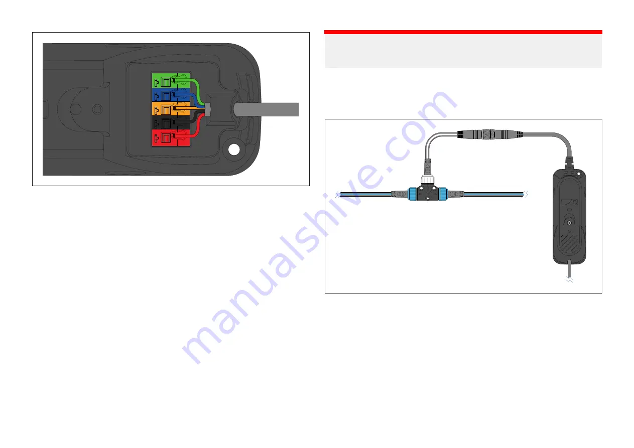
1. Feed the bare-ended wires and cable insulation/sheath through the cable
seal.
Ensure that the cable insulation/sheath protrudes slightly from the cable
seal.
2. Press and hold down the clamp release button for the relevant connection
terminal.
3. Feed the relevant colored cable into the open connection clamp.
Ensure that the stripped wire is pushed in to the terminal as far as it can
go. There should be minimal or no exposed wire showing.
4. Release the clamp release button.
5. Check that the wire has been correctly clamped into the terminal.
6. Repeat steps 2 to 4 for all wires.
7. Replace the gateway cover and ensure that the cover clips are fully
engaged.
8. Secure the cover by tightening the captive retaining screw until it is hand
tight.
Important:
To prevent water ingress, the gateway’s cover MUST be fitted in all
installations.
11.4 Connecting the gateway to the network
The gateway must be connected to a SeaTalkng ® / NMEA 2000 network.
1. Connect the gateway’s DeviceNet connector to the DeviceNet connector
on the supplied SeaTalkng ® to DeviceNet adaptor cable.
2. Connect the SeaTalkng ® connector on the supplied SeaTalkng ® to
DeviceNet adaptor cable to an available spur connection on the
SeaTalkng ® network.
Alternatively, connect the gateway’s DeviceNet connector directly to an
available DeviceNet spur on a DeviceNet network.
40
Summary of Contents for RSW-Wired
Page 2: ......
Page 4: ......
Page 16: ...CHAPTER 4 PARTS SUPPLIED CHAPTER CONTENTS 4 1 Parts supplied page 17 16...
Page 36: ...CHAPTER 10 GROUND CONNECTION CHAPTER CONTENTS 10 1 Gateway ground connection page 37 36...
Page 45: ...CHAPTER 13 MAINTENANCE CHAPTER CONTENTS 13 1 Service and maintenance page 46 Maintenance 45...
Page 68: ......
Page 71: ...WEEE Directive 8 What s in the box 17 Wind transducer Configuration 42 44 Wire stripping 39...
Page 72: ......
Page 73: ......


