12
SmartPilot X-5 Tiller & GP Tiller Installation & Setup Guide
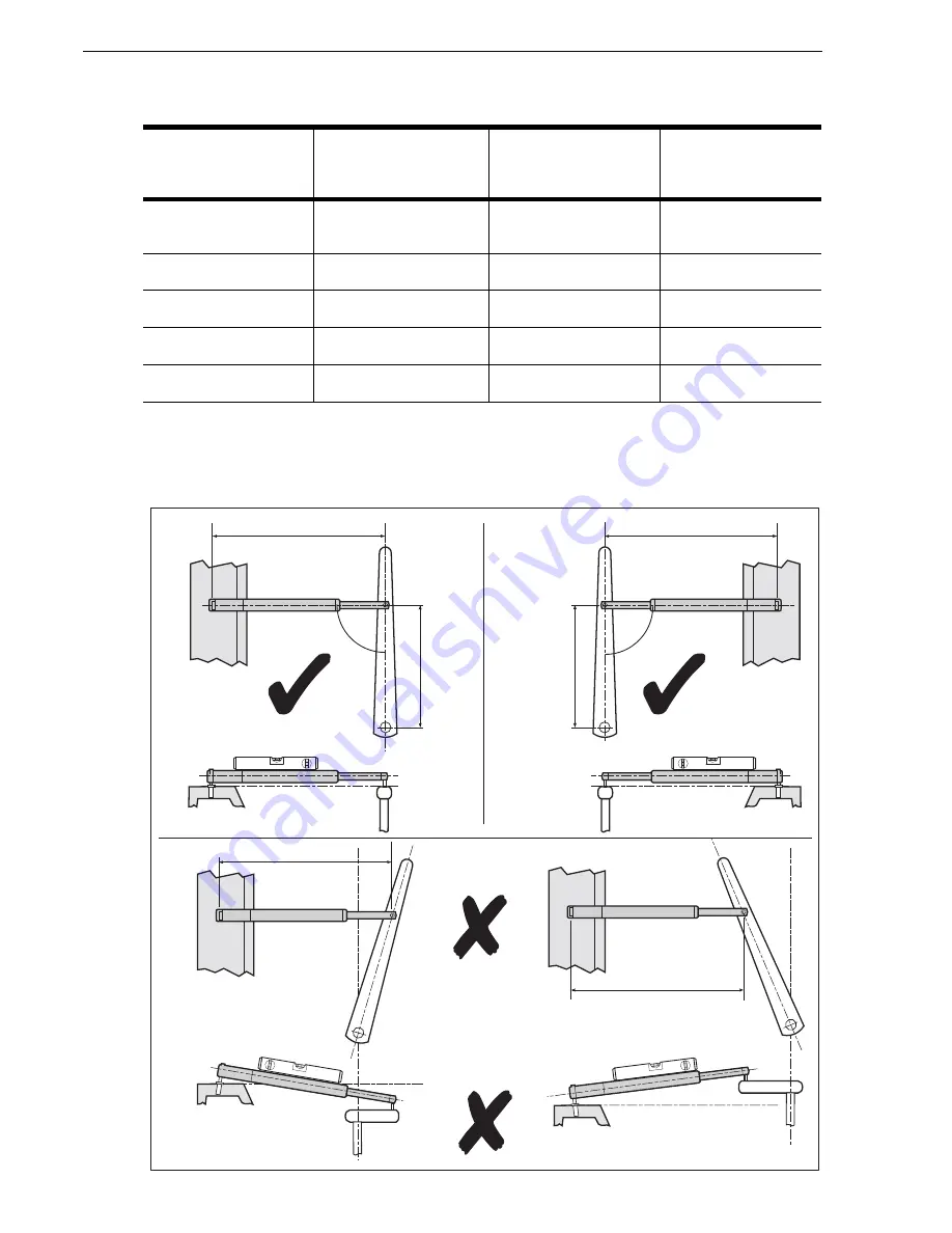
Use the following table to determine the required position for your vessel.
The Tiller drive mounting arrangement is shown in the following illustration. In the
following, dimension A represents the required distance between the tiller pin and the
center of the rudder stock, as determined from the above information.
Drive pin
distance from
rudder stock
Max degrees of
helm (with pilot
engaged)
Rate of helm
change
Force at rudder
457 mm (18”)
standard distance
31º
8 º per second
84 kgf
432 mm (17”)
33º
8 º per second
79 kgf
406 mm (16”)
35º
9 º per second
75 kgf
381 mm (15”)
37º
9 º per second
70 kgf
356 mm (14”)
39º
10 º per second
65 kgf
620mm (24.5")
620mm (24.5")
D10649-1
Dimension
A
Dimension
A
90
o
90
o
620mm (24.5")
620mm (24.5")
Summary of Contents for SmartPilot X5
Page 38: ...30 SmartPilot X 5 Tiller GP Tiller Installation Setup Guide ...
Page 52: ...44 SmartPilot X 5 Tiller GP Tiller Installation Setup Guide ...
Page 68: ...60 SmartPilot X 5 Tiller GP Tiller Installation Setup Guide ...
Page 72: ...64 SmartPilot X 5 Tiller GP Tiller Installation Setup Guide ...
Page 76: ......


