O
FF
ON
FLUXGATE
FAULT
S LEEP
FAULT
,
3
A
M
P
,
3
A
M
P
NMEA
0V 10V
0V
0V
R
UDDER J ET S IGNAL
CAN
C
A
N
,1
A
M
P
0V 10V
2
1
3
4
D10458-3
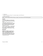
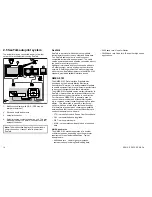
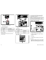
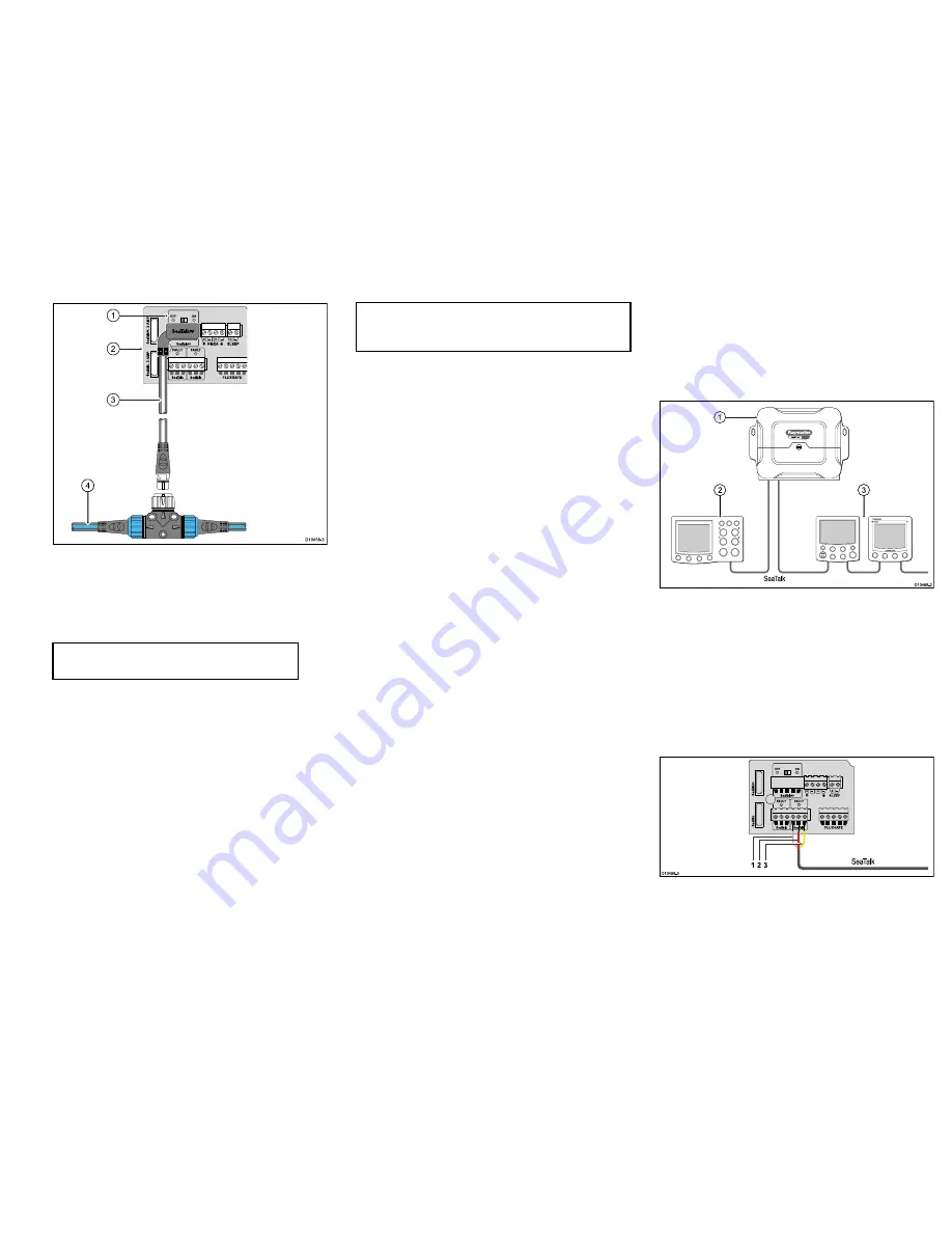
1.
SeaTalk
ng
power switch.
2.
Course computer connector panel.
3.
SPX to SeaTalk
ng
spur cable.
4.
SeaTalk
ng
backbone.
Note:
The connection at the backbone may be
into a T-piece or 5–way connector (not shown).
SeaTalk
ng
power switch
The course computer can provide power to the
SeaTalk
ng
backbone. This will provide power to certain
equipment connected to the backbone (e.g. ST70 pilot
controller and instruments).
Set the SeaTalk
ng
power switch on the connector panel
to the appropriate position:
•
ON
— The course computer will supply power to the
SeaTalk
ng
backbone. Ensure that there are no other
power feeds connected into the backbone.
•
OFF
— The course computer will not supply power
the SeaTalk
ng
backbone. Ensure that there is a
separate power feed to the SeaTalk
ng
backbone.
Important:
Use correct fuse. The fuse supplying
the SeaTalk
ng
system MUST be rated as per the
value shown on the connector panel.
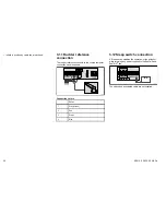
3.8 SeaTalk connection
The SPX course computer has 2 SeaTalk connectors
available. It is recommended that 1 of these is reserved
for connection to the primary autopilot controller.
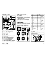
Example SeaTalk autopilot
S
eaTalk
SMART
PILOT
D10468-2
2
3
1
1.
SPX course computer.
2.
Helm position with primary autopilot controller (on
dedicated SeaTalk connection).
3.
Helm position with secondary autopilot controller
and instrument(s).
SPX to SeaTalk connection
Use a SeaTalk cable. Depending upon the SeaTalk
cable obtained, you may need to remove the connector
from one end to reveal the cable cores.
SeaTalk
D10459-3
OFF
ON
FLUXGATE
FAULT
S LEEP
FAULT
3
1 2
Cables and connections
23
Summary of Contents for SPX 10
Page 2: ......
Page 4: ......
Page 6: ...6 SPX10 SPX30 SPX SOL ...
Page 30: ...30 SPX10 SPX30 SPX SOL ...
Page 36: ...36 SPX10 SPX30 SPX SOL ...
Page 37: ......
Page 38: ...www raymarine com ...

