background image


Distributed by 


Any reference to Raytheon or 

RTN in this manual should be 

interpreted as Raymarine. 

The names Raytheon and RTN 

are owned by the 

Raytheon Company. 


Summary of Contents for ST40

Page 1: ...Distributed by Any reference to Raytheon or RTN in this manual should be interpreted as Raymarine The names Raytheon and RTN are owned by the Raytheon Company...

Page 2: ...ST40 Compass Instrument Owner s Handbook Document number 81161_2 Date 1stMay2001...

Page 3: ...Copyright Raymarine Limited 2001...

Page 4: ...ntheleisuremarineenvironment ThedesignandmanufactureofRaymarineequipmentandaccessories conformtotheappropriateElectromagneticCompatibility EMC standards butcorrectinstallationisrequiredtoensurethatper...

Page 5: ...ii ST40CompassInstrumentOwner sHandbook...

Page 6: ...encing alarms 1 Backlighting and contrast adjustment 3 Compass heading screen 4 Locked heading screen 4 1 4 Alarms 5 Off course active alarm 5 Enabling disabling alarm 5 Man overboard alarm repeated 5...

Page 7: ...es 15 Fitting Fluxgate Compass transducer 15 Introduction 15 Stand alone instrument 15 System requirements 15 Installation 15 Running transducer cable 16 Connections to the instrument 17 Stand alone c...

Page 8: ...face ThankyouforpurchasingaRaymarineproduct Wearesureyour ST40instrumentwillgiveyoumanyyearsoftrouble freeoperation Thisinstrumentisdesignedtoprovidereliableperformance even underthemostdemandingcondi...

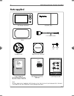
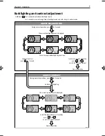
Page 9: ...If any item is not present contact your Raymarine Dealer Adjusting display backlighting contrast Normal operation ST40 Compass Instrument quick reference guide or To exit adjust mode press or wait for...

Page 10: ...to ensureoptimumperformanceonyourvessel DoNOTusethe instrumentuntilthecalibrationprocedureshavebeen satisfactorilycompleted usingtheproceduresinChapter4 Calibration ColouredbezelandDesktopMountingBra...

Page 11: ...ed heading Autopilot sets auto lock COMPASS ST40 Increase Decrease 3 seconds Alarm on off Set off course alarm threshold COMPASS STEER STEER STEER STEER ST40 COMPASS ST40 COMPASS ST40 COMPASS ST40 To...

Page 12: ...IGHTING or wait for 5 second timeout or press D4856 1 The current contrast level is displayed Select the required contrast level then or press Normal operation ADJUST CONTRAST or wait for 5 second tim...

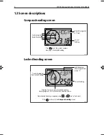
Page 13: ...compass bearing as the locked heading D4774 2 Locked heading screen D4775 2 Locked heading Either magnetic M or true T Current heading Press to return to the Compass heading screen Adjust locked head...

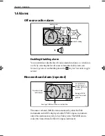
Page 14: ...ldingdownthe keyfor3seconds toggle action Man overboard alarm repeated Current distance from MOB event in either metres M or yards Y Bearing of MOB event from current position Direction to steer to MO...

Page 15: ...6 ST40CompassInstrumentOwner sHandbook...

Page 16: ...able youtogetthebestpossibleperformancefromyourRaymarine equipment guidelinesaregivenintheinstallationinstructions to enableyoutoensureminimuminteractionbetweendifferentitems ofequipment i e ensureopt...

Page 17: ...ceandre secure 2 2 Fault finding Preliminary procedures Ifyouappeartohaveaproblem firstcheckthesecurityofthe connectionsattherearoftheinstrumentandreconnectanythatare loose Changesintheelectronicenvir...

Page 18: ...efluxgate compasstransducercableandthe securityoftheconnections No heading information Low battery Display blank D4778 2 COMPASS ST40 Action ChecksecurityofSeaTalk connectionsbetweeninstruments Checkc...

Page 19: ...lk instruments not working Action CheckthesecurityofSeaTalk connectorsbetweenfunctioningand non functioninginstruments D4758 2 WIND ST40 WIND ST40 WIND ST40 Assistance Ifyouareunabletorectifyanyproble...

Page 20: ...rm underallconditions itisimportanttounderstandwhatfactorscould affecttheoperationoftheproduct TheguidelinesgivenheredescribetheconditionsforoptimumEMC performance butitisrecognisedthatitmaynotbepossi...

Page 21: ...tailedintheinstallation manual Ifasuppressionferriteisattachedtoacable thisferriteshouldnot beremoved Iftheferriteneedstoberemovedduringinstallationit mustbereassembledinthesameposition Suppression Fe...

Page 22: ...r extra tools may be required Site requirements Fluxgate Compass transducer The Fluxgate Compass transducer should be positioned as near as possible to the pitch roll centre of the vessel as shown in...

Page 23: ...r magnetic items engines communications equipment or cabling On a vertical mounting surface Where necessary make up a suitable nonferrous wedged packing piece to provide the necessary verticalsurface...

Page 24: ...r and connectitdirectlytotheinstrument System requirements If you intend fitting the ST40 Compass instrument as part of an instrument system you must ensure that only one Fluxgate Compass transducer i...

Page 25: ...greater than 10 on any heading then thesiteissuitablefortheFluxgateCompasstransducer Using the self tapping screws provided mount the Fluxgate Compass transducer vertically on a suitable bulkhead so...

Page 26: ...25028 Whenconnectedinthismanner powercanbeprovidedfromthe SeaTalkbus e g fromtheautopilot ProvidedthereisnootherFluxgateCompassalreadyconnectedto SeaTalk youcanconnecttheinstrumenttoboththecompass tra...

Page 27: ...mentisprotectedbya3Afuseorcircuitbreaker 3 A circuit breaker Red ve Uninsulated wire screen ve _ D4779 2 Connections to a stand alone instrument Cable from Fluxgate Compass transducer Screen Blue Gree...

Page 28: ...ve D4827 2 Typical SeaTalk connections SeaTalk bus SeaTalk bus SeaTalk interface kit Power cable Note A 5 A fuse can be used in place of the circuit breaker if preferred Fitting the instrument Fityou...

Page 29: ...20 ST40CompassInstrumentOwner sHandbook 2 Cut hole 57 mm 2 25 in cutter D4760 1 Peel protective sheets from gasket 3 D4770 1 4 Stick gasket to rear of instrument D4761 1...

Page 30: ...1 6 Feed cables through clamping bracket connect cables then secure instrument with bracket and thumb nut Desktop Mounting Bracket AnoptionalDesktopMountingBracket PartNo E25024 enablesyou tomountyou...

Page 31: ...ountyourST40instrument dosoinaccordancewiththe InstructionSheet whichisincludedwiththeDesktopMounting Bracket 3 3 Calibration requirement Onceinstallationiscompleteandbeforeyouuseyourinstrument carry...

Page 32: ...wisestated EMC conformance Alwayschecktheinstallationbeforegoingtoseatomakesurethatit isnotaffectedbyradiotransmissions enginestartingetc 4 2 User calibration Usercalibrationenablesyouto Setthecompass...

Page 33: ...on HDGT To bypass linearisation When linearisation successful 3 beeps To linearise compass If vessel is turned too fast during linearisation a SLO legend is displayed CAL During normal operation for a...

Page 34: ...strument status COMPASS CAL During normal operation for approximately 2 seconds hold down and To return to normal operation from either screen ST40 COMPASS ST40 Note If there is no key activity when t...

Page 35: ...ion access Boat show mode COMPASS ST40 CAL Return to normal operation with factory defaults applied If If COMPASS ST40 CAL COMPASS COMPASS ST40 CAL During normal operation for approximately 2 seconds...

Page 36: ...thmaximumbacklighting Operating temperature 0 Cto 70 C Interfaces SeaTalk Overall dimensions 126mmx70mmx38mm 5 00inchesx2 80inchesx1 55inches Boss diameter 55mm 2 20inches Heading range 0 to 359 Off c...

Page 37: ...28 ST40CompassInstrumentOwner sHandbook...

Page 38: ...sare from1 slowresponse to15 fastresponse SeaTalk SeaTalkisaproprietaryRaymarinesystemwhichlinksdifferent compatibleproducts toprovideasingle integratednavigationalsystem SeaTalkcanalsocommunicatewith...

Page 39: ...30 ST40CompassInstrumentOwner sHandbook...

Page 40: ...3 installation guidelines 11 F Factory defaults 25 Fault finding 8 assistance 10 blank display 9 low battery 9 no heading information 9 SeaTalk problems 9 Fluxgate Compass transducer checking suitabil...

Page 41: ...res 1 5 Operating temperature 27 P Panel lighting 3 Parts supplied vi S Servicing and safety 7 Setting backlighting 3 compass heading response 24 contrast 3 heading alignment 24 locked heading respons...

Page 42: ...D4800 1 TOP Cut out shaded area only Cut out hole 57 mm 2 25 in diameter ST40 Instrument Template...

Page 43: ......

Page 44: ...in impeller carriers impellers impeller bearings and impeller shaft are specifically excluded from this Warranty Magnetrons Cathode Ray Tubes CRT TFT Liquid Crystal Displays LCD and cold cathode fluo...

Page 45: ...Telephone 1 800 539 5539 Ext 2333 or 1 603 881 5200 Ext 2333 Customer Support Telephone 44 0 23 9271 4713 Fax 44 0 23 9266 1228 Technical Support Telephone 1 800 539 5539 Ext 2444 or 1 603 881 5200 Ex...

Reviews: