4
ST600R Autopilot Control Unit
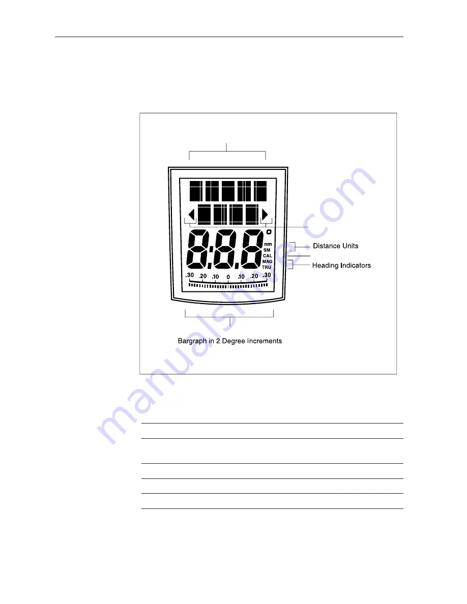
2.2 Display Layout
The following illustration shows all the elements, together with a
brief description, that make up the ST600R autopilot LCD display.
Rudder or Steer Direction Indicator
D3682-1
Variable Text Region
(5+4 Characters/Digits Maximum)
Calibration Indicator
Port and Starboard
Direction to Steer
Indicators
• The bar graph at the bottom of the display is normally the rudder bar.
If it has been set as a direction-to-steer indicator (refer to User
Setup), the display depends on the current mode (see below).
Mode
Bar
Standby
Not used (rudder angle if feedback transducer is
connected to autopilot)
Auto
Heading error bar
Track
Cross track error (XTE) bar, in 0.02nm increments
Vane
Wind angle error bar
• If neither distance units (nm or SM) is displayed, the distance is in
Km.
Summary of Contents for ST600R
Page 2: ...ST600R Autopilot Control Unit Owner s Handbook Document number 81134 3 Date May 2001 ...
Page 3: ......
Page 5: ...ST600RAutopilotControlUnit ii ...
Page 24: ...13 Chapter2 BasicOperation SeaTalk Data Chart ...
Page 41: ...30 ST600RAutopilot ControlUnit ...


