background image

 Installation

                             15

Convenience- the mounting location should be easily
accessible to allow operation of the controls and should
enable easy viewing of the display.

Installation angle- the display should be mounted at an
angle. Mounting it in a flat plane is not recommended due to
increased heat absorption.

Viewing angle - this LCD has been chosen to give the very
best performance, including viewing angle. However, the
contrast and colors seen on all LCD displays vary slightly
with viewing angle.

Access


- there must be sufficient space behind the display

to allow cable connections to the rear connectors, avoiding
tight bends in the cable.

Interference - the selected location should be far enough
away from devices that may cause interference, such as
motors, generators and radio transmitters/receivers.

Magnetic compass - mount the display at least 1 metre (3
ft.) away from a magnetic compass.

Environment - to prevent overheating, do not restrict airflow
at the rear of the display unit; ensure that there is adequate
ventilation, particularly if the display unit is pod-mounted. If
the space behind the display is air conditioned or cooled by a
fan , it will help in keeping the unit’s temperature down when
mounted in direct sunlight. 
FAILURE TO ADEQUATELY VENTILATE THE UNIT 
COULD INVALIDATE YOUR WARRANTY.
The display should be protected from physical damage and 
excessive vibration. Although the display unit is waterproof 
from the front when installed correctly, it is good practice to 
mount it in a protected area away from prolonged and direct 
exposure to rain and salt spray. DO NOT place the display 
near to a heat source.

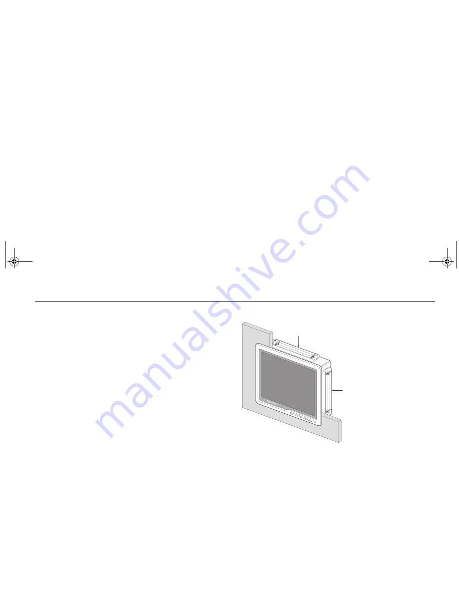
Mounting options


Your monitor can be
installed using the
mounting brackets
(supplied) in either the
horizontal or vertical
keyways.

Make sure that both
brackets are in the
same orientation
(either both vertical or
both horizontal).

IP address label

You will find a removeable label on your display with an IP
address that will be required to ensure communication with other
Raymarine products. 

Before installing your monitor carefully remove this label and
attach it to this handbook or a suitable log book for future
reference.

Horizontal fixing

Vertical 

fixing

81277_1.book  Page 15  Thursday, August 17, 2006  1:51 PM

Summary of Contents for Viewable Marine Displays

Page 1: ...Raymarine Sunlight Viewable Marine Displays Users Guide Document Number 81277_1 Date August 2006 81277_1 book Page 1 Thursday August 17 2006 1 51 PM...

Page 2: ...major marketing territories AST Autoadapt Auto GST Autoseastate Autotrim Bidata Marine Intelligence Maxiview On Board Raychart Raynav Raypilot Raystar ST40 ST60 Seaclutter Smart Route Tridata and Way...

Page 3: ...er cable 14 Cable runs 14 CAUTION 14 Display location and mounting options 14 Mounting options 15 IP address label 15 Installation 16 Preparing the installation site 16 Installing the display 16 Rear...

Page 4: ...ii Raymarine Sunlight Viewable Marine Displays Users Guide 81277_1 book Page ii Thursday August 17 2006 1 51 PM...

Page 5: ...ve the display unit cover or attempt to service the equipment WARNING Lightning strikes To prevent damage caused by lightning or abnormal current peaks disconnect the display from the power source dur...

Page 6: ...for use on boats with positive ground The power input cable earth screen connections must be connected directly to the boats ground CAUTION Thermal circuit breaker If you do not have a thermal circuit...

Page 7: ...ver limitations to the amount of heat the display can absorb before developing problems If temperatures exceed the normal temperature operating range the display could overheat and begin to blackout d...

Page 8: ...4 Raymarine Sunlight Viewable Marine Displays Users Guide 81277_1 book Page 4 Thursday August 17 2006 1 51 PM...

Page 9: ...his hand book to the best of our knowledge was correct as it went to press However our policy of continuous improvement and updating may change product specifications without prior notice As a result...

Page 10: ...a few minutes to fill out the warranty card included in the box or go to www raymarine com It is important that you complete the owner information and return the card to receive full warranty benefits...

Page 11: ...turn the display ON or OFF Press to display a list of assigned inputs OSD control buttons Press as required to select video inputs access secondary functions or navigate through the OSD menu Display...

Page 12: ...aTalkhs Ethernet port will allow a level of OSD controlfrom a compatible Raymarine product but does not have full SeaTalkhs compatibility as it will not show video data over the network Exhaust fan In...

Page 13: ...lations using a Raymarine display CANCEL OK RANGE IN OUT PAGE ACTIVE WPTS MOB MENU DATA Power IN from ship s supply DVI Input DVI Output VGA Input VGA Output VGA Input VGA Output Composite video S vid...

Page 14: ...10 Raymarine Sunlight Viewable Marine Displays Users Guide 81277_1 book Page 10 Thursday August 17 2006 1 51 PM...

Page 15: ...3 ft 1m from any equipment transmitting or cables carrying radio signals e g VHF radios cables and antennas In the case of Single Side Band SSB radios the distance should be increased to 7 ft 2m More...

Page 16: ...Mounting brackets x 2 RO8174 5 meter VGA cable assembly E55055 10m E Series VGA cable assembly E55056 20m E Series VGA cable assembly E06021 5 meter DVI D cable assembly Note E Series VGA cables have...

Page 17: ...nnections The power connection to the display should be made at either the output of the battery isolator switch or at a DC power distri bution panel Raymarine recommends that power is fed directly to...

Page 18: ...otected from physical damage and exposure to heat Avoid running cables through bilges or doorways or close to moving or hot objects Acute bends must be avoided Where a cable passes through an exposed...

Page 19: ...ion particularly if the display unit is pod mounted If the space behind the display is air conditioned or cooled by a fan it will help in keeping the unit s temperature down when mounted in direct sun...

Page 20: ...plate 4 Using a suitable file smooth the edges of the aperture Installing the display 1 Carefully insert the monitor into the aperture ensuring that the gasket on the rear of the fascia lays flat agai...

Page 21: ...le screwdriver tighten the mounting bracket screws to secure the monitor in position 4 Connect all cables as required see Rear connections on this page Rear connections The rear connectors are The sel...

Page 22: ...18 Raymarine Sunlight Viewable Marine Displays Users Guide 81277_1 book Page 18 Thursday August 17 2006 1 51 PM...

Page 23: ...t to the display Control functions enable you to change the appearance of the display Power Power ON To power your monitor ON press and hold the POWER button for 3 seconds Power OFF To power your moni...

Page 24: ...ng the following button presses Control name Control tab Sub menu Menu 1 Press and hold to show the OSD menu 2 Press the Menu button to move between the 7 tabs Tabs are highlighted from left to right...

Page 25: ...within the main display screen The position of this inset can be moved to suit your personal preference The PIP sub menu enables you to set up how the PIP appears on screen and has eleven options On...

Page 26: ...source With the display powered ON press the button corresponding to the input source required for the main screen The selected source is shown in the bottom right hand corner of the display Layout T...

Page 27: ...ion of the PIP can only be changed when Child is selected A sliding bar with settings between 0 100 appears Use the left and right buttons to increase or decrease the value as appro priate Increasing...

Page 28: ...lue as appropriate PIP Image Sharpness Adjusts the sharpness of the PIP image A sliding bar with settings between 0 100 appears Use the left and right buttons to increase or decrease the value as appr...

Page 29: ...Horizontal position Vertical position Color Tint Sharpness Brightness Adjusts the display backlighting A sliding bar with settings between 0 100 appears Use the left and right buttons to increase or d...

Page 30: ...priate Vertical position Adjusts the vertical position of the main screen A sliding bar with settings between 0 100 appears Use the left and right buttons to increase or decrease the value as appropri...

Page 31: ...One Use the left and right buttons switch between the 3 options Fill All stretches the input signal to fill the main screen Fill Aspect the input signal maintains a specific aspect ration Fill One to...

Page 32: ...ng bar with settings between 0 100 appears Use the left and right buttons to increase or decrease the value as appropriate Factory reset Enables all values to be reset to their factory defaults Highli...

Page 33: ...y available when User is selected and adjusts the blue color temperature The left and right buttons increase or decrease the value on a sliding bar calibrated from 0 255 Any change occurs as the butto...

Page 34: ...on will change the video input in the PIP window Press and hold ENTER to exit PIP Input mode The PIP remains open with the last input source selected Brightness Press and hold for 1 second the brightn...

Page 35: ...ergent to remove grease marks Disconnecting the power supply To disconnect the display from the boat s power supply either Isolate the power cable from the main supply or Remove the power connector fr...

Page 36: ...sure that the power supply cable is sound and that all connections are tight and free from corrosion 2 Check the system fuse The display shows the message No Input Check that the video source i e dis...

Page 37: ...1 432 17 00 D 335 13 19 366 14 41 E 100 3 94 100 3 94 Dimension in mm inch Approvals CE conforms to FCC conforms to 1999 5 EC EN60945 2002 Part 80 47CFR and Part 2 47CFR Waterproof IP66 from the front...

Page 38: ...ize G170 17 display G190 19 display Video inputs 3 VGA 2 DVI D 3 Composite video 1 S Video Connectors Power VGA DVD D Composite video S Video Ethernet Serial Port Native resolution 1280 x 1024 SXGA Re...

Reviews: